892
Network Instructions Section 3-24
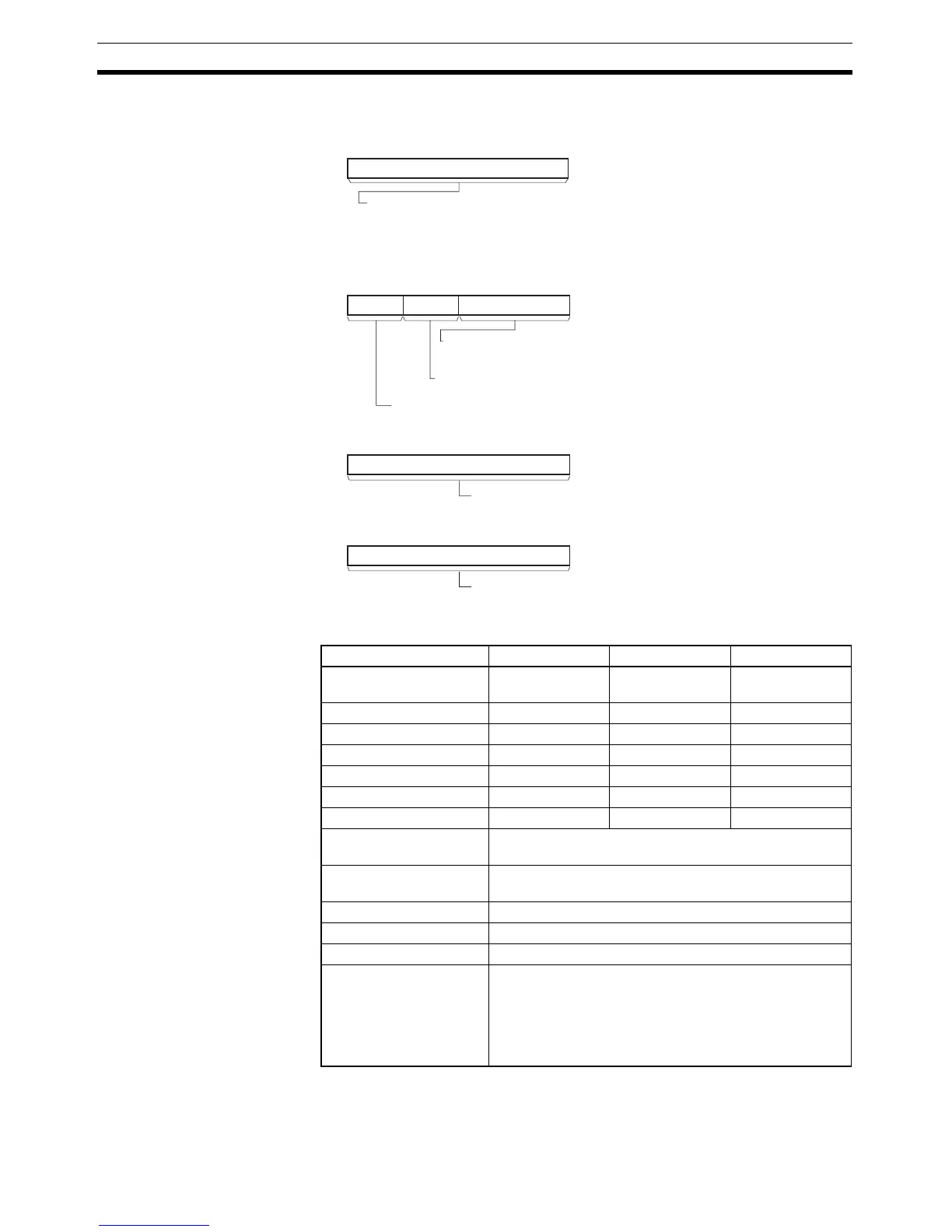
C: First control word
Specifies the first of four control words (C to C+3).
Operand Specifications
Description Sends the “read information/status” explicit message command (stored in
words S+1 to S+3) to the node address specified in S, via the Communica-
tions Unit with the FINS unit address specified in bits 00 to 07 of C+1.
C
0
15
C+1
8
111215
07
C+2
15
0
C+3
15
0
Set the maximum number of words of data in the received data beginning at D.
The allowed setting range is 0 to 010C hex (268 words).
If the number of words of received data exceeds the value set here, a FINS
error will occur (response too long, code 11 0B) and no data at all will be stored
(in the area starting at D+3).
If the number of words of received data is less than the value set here, the
remaining words (in the area starting at D+3) will be left unchanged.
FINS unit address of relaying Communications Unit.
CPU Bus Unit: 10 to 1F hex (unit number + 10 hex)
Special I/O Unit: 20 to 7F hex (unit number + 20 hex)
Port number of the communications port (logical port) for the network
instruction: 0 to 7 hex (F hex: Automatic allocation)
Byte order of service data (frame data) stored in areas beginning at S+6 and D+3
0 hex: Stored from leftmost byte (Left → Right → Left → Right ...)
8 hex: Stored from rightmost byte (Right → Left → Right → Left ...)
Response monitoring time
0001 to FFFF hex (0.1 to 6553.5 s)
0000 hex: 2 s (default setting)
Explicit message format
0000 hex: DeviceNet (same as using the 2801 FINS command)
Area S D C
CIO Area CIO 0 to
CIO 6140
CIO 0 to
CIO 6143
CIO 0 to
CIO 6140
Work Area W0 to W508 W0 to W511 W0 to W508
Holding Bit Area H0 to H508 H0 to H511 H0 to H508
Auxiliary Bit Area A0 to A956 A0 to A959 A0 to A956
Timer Area T0000 to T4092 T0000 to T4095 T0000 to T4092
Counter Area C0000 to C4092 C0000 to C4095 C0000 to C4092
DM Area D0 to D32764 D0 to D32767 D0 to D32764
Indirect DM addresses in
binary
@ D0 to @ D32767
Indirect DM addresses in
BCD
*D0 to *D32767
Constants ---
Data Registers ---
Index Registers ---
Indirect addressing using
Index Registers
,IR0 to ,IR15
–2048 to +2047, IR0 to –2048 to +2047, IR15
DR0 to DR15, IR0 to IR15
,IR0+(++) to ,IR15+(++)
,–(– –)IR0 to, –(– –)IR15