895
Network Instructions Section 3-24
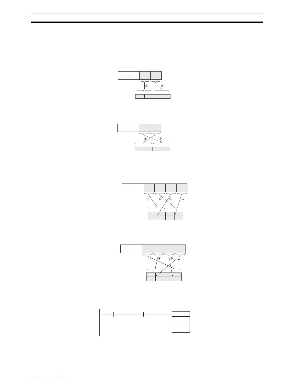
The following diagrams show how data is stored in the data areas when the
service data is in 2-byte or 4-byte units.
1. Data in 2-byte Units
• Storing Data from the Leftmost Byte (Bits 12 to 15 of C = 0 hex)
Example: Storing the value 1234 hex in D+1
• Storing Data from the Rightmost Byte (Bits 12 to 15 of C = 8 hex)
Example: Storing the value 1234 hex in D+1
2. Data in 4-byte Units
• Storing Data from the Leftmost Byte (Bits 12 to 15 of C = 0 hex)
Example: Storing the value 12345678 hex in D+1 and D+2
• Storing Data from the Rightmost Byte (Bits 12 to 15 of C = 8 hex)
Example: Storing the value 12345678 hex in D+1 and D+2
Example In this example, EGATR(721) is used to read the general status of a DRT2
Slave (I/O Terminal).
34
15
34 1D+1 2
08 07
00
12
Frame
The data in the frame is
in the order 34 → 12.
In this case, 1234 hex is
stored from the leftmost
byte in the order 34 → 12.
34
15
12 3D+1 4
08 07
00
12
Frame
The data in the frame is in
the order 34 → 12.
In this case, 1234 hex is
stored from the rightmost
byte in the order 34 → 12.
78
15
78 5D+1
D+2
6
34 12
08 07
00
56 34 12
Frame
The data in the frame is in the
order 78 → 56 → 34 → 12.
In this case, 12345678 hex is
stored from the leftmost byte in
the order 78 → 56 → 34 → 12.
78
15
56 7D+1
D+2
8
12 34
08 07
00
56 34 12
Frame
In this case, 12345678 hex is
stored from the rightmost byte in
the order 78 → 56 → 34 → 12.
The data in the frame is in the
order 78 → 56 → 34 → 12.
0.00
A202.06
S
D
C
EGATR
D0
D100
D200
Communications Port
Enabled Flag (Port 6)