908
Network Instructions Section 3-24
Operand Specifications
Description Writes the specified number of words beginning at S from the local CPU Unit
to the write destination beginning at D in the remote CPU Unit with the node
address specified in C.
Note ECHWR(724) sends an explicit message with the Service Code 1E hex (Byte
Data Write).
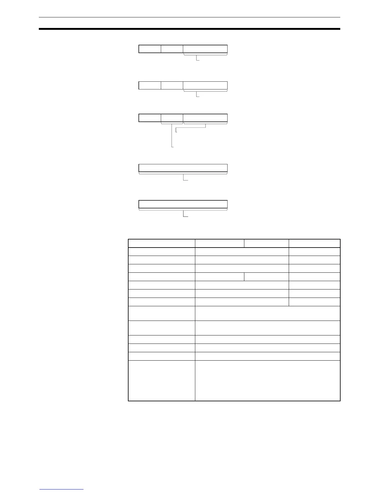
C+2 0
8
111215
07
C0 0
8
111215
07
C+1 0 0
8
111215
07
C+3
15
0
C+4
15
0
FINS unit address of relaying Communications Unit.
• CPU Bus Unit: 10 to 1F hex (unit number + 10 hex)
• Special I/O Unit: 20 to 7F hex (unit number + 20 hex)
Port number of the communications port (logical port)
for the network instruction: 0 to 7 hex
(F hex: Automatic allocation)
Source node address (remote CPU Unit)
(00 to maximum node address (hex))
Example: DeviceNet: 00 to 3F hex (0 to 63)
Write data size (words):
01 to 64 hex (1 to 100 words)
Response monitoring time
0001 to FFFF hex (0.1 to 6553.5 s)
0000 hex: 2 s (default setting)
Explicit message format
0000 hex: DeviceNet (same as usin
Area S D C
CIO Area CIO 0 to CIO 6143 CIO 0 to CIO 6139
Work Area W0 to W511 W0 to W507
Holding Bit Area H0 to H511 H0 to H507
Auxiliary Bit Area A0 to A959 A448 to A959 A0 to A955
Timer Area T0000 to T4095 T0000 to T4091
Counter Area C0000 to C4095 C0000 to C4091
DM Area D0 to D32767 D0 to D32763
Indirect DM addresses in
binary
@ D0 to @ D32767
Indirect DM addresses in
BCD
*D0 to *D32767
Constants ---
Data Registers ---
Index Registers ---
Indirect addressing using
Index Registers
,IR0 to ,IR15
–2048 to +2047, IR0 to –2048 to +2047, IR15
DR0 to DR15, IR0 to IR15
,IR0+(++) to ,IR15+(++)
,–(– –)IR0 to, –(– –)IR15