951
Failure Diagnosis Instructions Section 3-28
3-28-3 FAILURE POINT DETECTION: FPD(269)
Purpose Diagnoses a failure in an instruction block by monitoring the time between
execution of FPD(269) and execution of a diagnostic output and finding which
input is preventing an output from being turned ON.
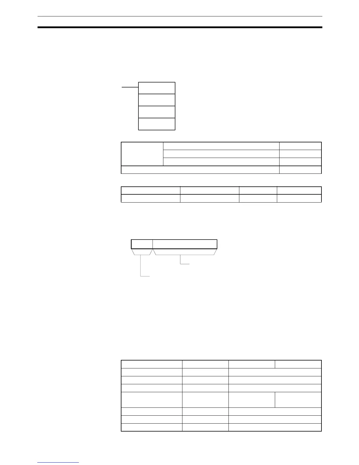
Ladder Symbol
Variations
Applicable Program Areas
Operands C: Control Word
C must be a constant between 0000 and 01FF or between 8000 and 81FF.
The following diagram shows the function of the digits in the control word.
T: Monitoring Time
T must be between 0 and 9,999 decimal (between 0000 and 270F hex). A
value of 0 disables time monitoring; values in the range of 1 to 270F set the
monitoring time from 0.1 to 999.9 seconds.
R: First Register Word
The functions of the register words are described on page 954.
Operand Specifications
FPD(269)
C
T
R
C: Control word
T: Monitoring time
R: First register word
Variations Executed Each Cycle for ON Condition FPD(269)
Executed Once for Upward Differentiation Not supported.
Executed Once for Downward Differentiation Not supported.
Immediate Refreshing Specification Not supported.
Block program areas Step program areas Subroutines Interrupt tasks
Not allowed OK OK Not allowed
15 01112
C
FAL number: 000 to 1FF
Diagnostic output mode
0: Bit address output only (hexadecimal)
8: Bit address and message output (ASCII)
Area C T R
CIO Area --- CIO 0 to CIO 6143
Work Area --- W0 to W511
Holding Bit Area --- H0 to H511
Auxiliary Bit Area --- A0 to A447
A448 to A959
A448 to A959
Timer Area --- T0000 to T4095
Counter Area --- C0000 to C4095
DM Area --- D0 to D32767