955
Failure Diagnosis Instructions Section 3-28
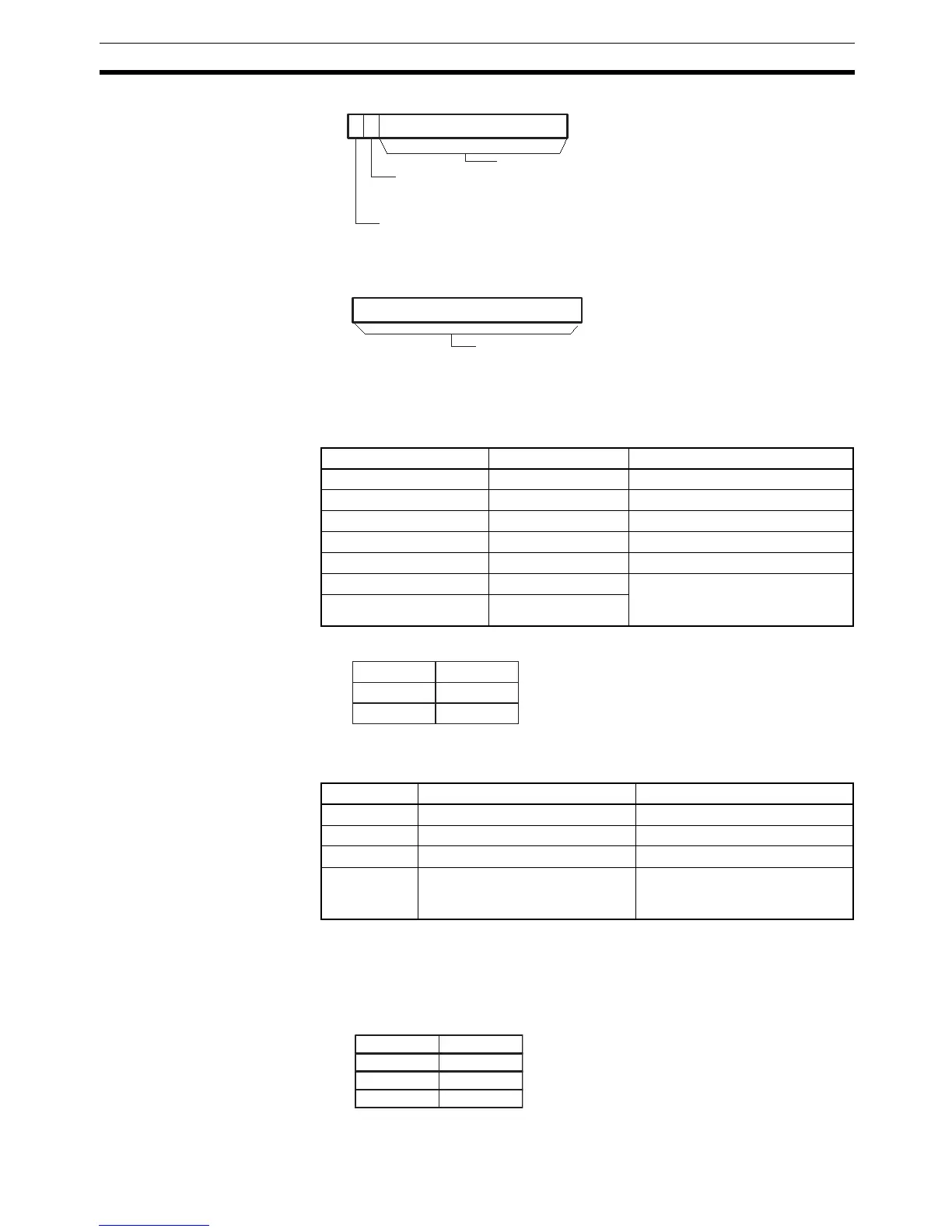
Register words R+2 to R+4 indicate the address of the input which prevented
the diagnostic output from being turned ON. The bit address is output to these
words in ASCII. The following table shows the ASCII representations for each
area.
Register words R+2 through R+5 would have the following values for
W511.15:
The user can store an ASCII message in register words R+6 to R+9. This
message will be displayed on the CX-Programmer if a non-fatal error is gener-
ated by the time monitoring function. Mark the end of the message with the
null character (00 hexadecimal).
Area ASCII text Notes
Auxiliary Area A0.00 to A959.15 ---
Holding Area H0.00 to H511.15 ---
Work Area W0.00 to W511.15 ---
CIO Area 0.00 to 6143.15 ---
Task Flags TK0 to TK1023 ---
Timer Area _T0 to _T4095 The “_” represents an ASCII
space.
(Character code 20.)
Counter Area _C0 to _C4095
Word Bits 8 to 15 Bits 0 to 7
R+2 W 5
R+3 1 1
R+4 1 5
R+5 2D (hexadecimal) Input type (hexadecimal)
30: Normally open
31: Normally closed
15 014
R
13
15
0
R+1
Not possible to use.
Input type
0: Normally open
1: Normally closed
Bit Address Found Flag
0: Not found yet
1: Bit address found
Not possible to use.
15
R+2
R+3
R+4
W 5
1 1
15
Bit address written in ASCII
15 8 07
R+6
R+7
R+8
R+9