3-1 Routing Table Overview
3-1-1 Definition of Routing Tables
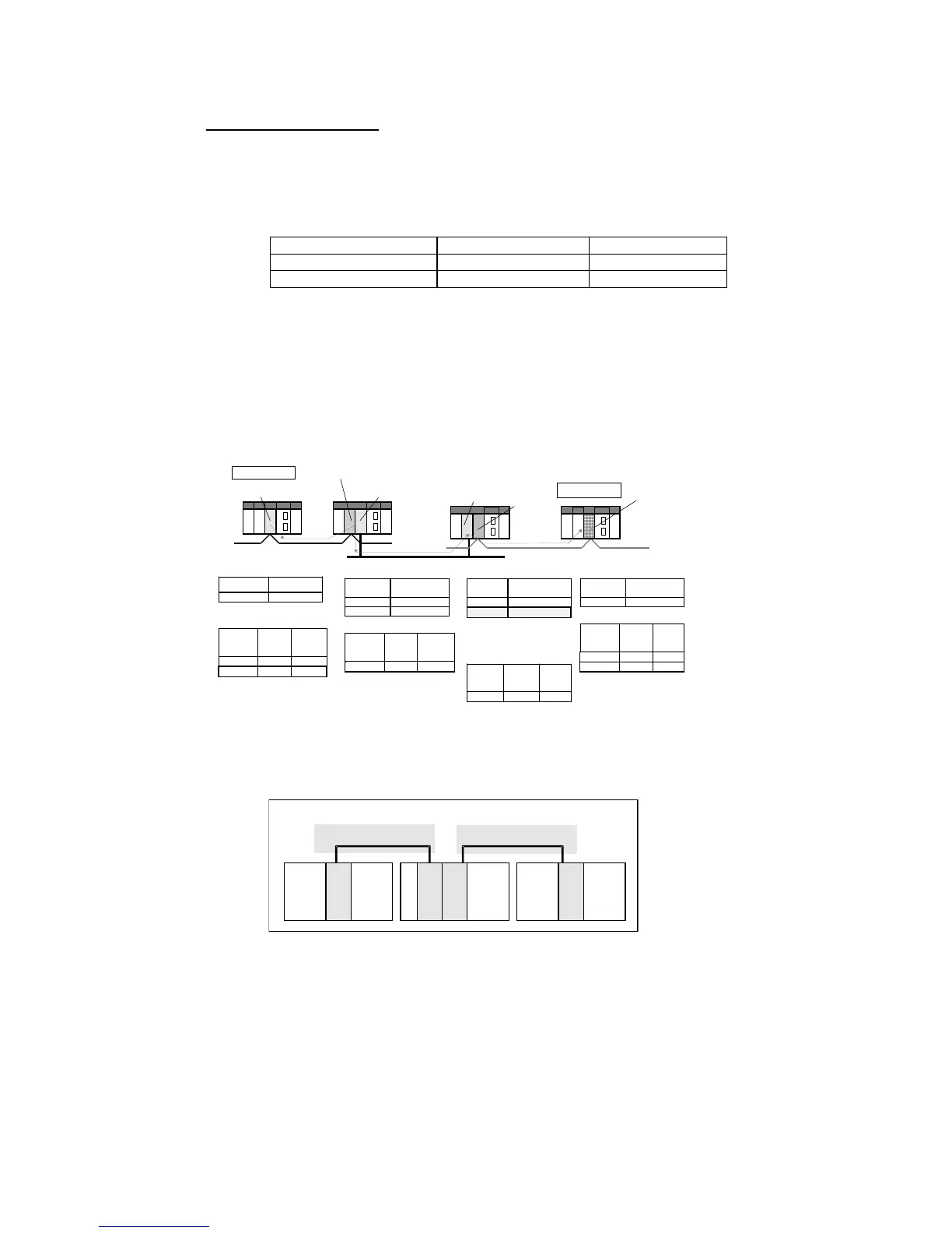
Relay Network Table
The relay network table indicates the network address and node address of the first
relay node when data is being sent to a destination network other than a network to
which the PLC is connected. The destination network is reached by following these
relay nodes.
Destination network address Relay network address Relay node address
Relay Network Table
Destination network address: Address (1 to 127) of the final destination network
Relay network address: Address (1 to 127) of the network containing the first relay node
in the path to the destination network
Relay node address: Node address of the first relay node in the path to the destination
network
Example: The following example shows the routing tables that route communications
from PLC1 (network address 1, node address 1) to PLC4 (network address 3, node
address 2).
PLC2 Local Network Table
Unit number Local network
address
0 1
1 2
PLC1 Relay Network Table
Destination
network
address
Relay
network
address
Relay
node
address
2 1 3
3 1 3
To go to network address 3, first it is
necessary to go to node address 3 in
network address 1.
PLC3 LOCAL NETWORK TABle
Unit number Local network
address
0 2
Node address 1
(Unit number 0)
Node address 3 (Unit number 0)
Relay node PLC2
Local node PLC1
Network address 1
Node address 1
(Unit number 1)
Relay node PLC3
Node address 2
(Unit number 0)
Network address 2
Node
address 1
(Unit
number 1)
Target node PLC4
Node address 2
(Unit number 0)
Network address 3 (destination network)
PLC1 Local Network Table
Unit number
Local network
address
0 1
PLC2 Relay Network Table
Destination
network
address
Relay
network
address
Relay
node
address
3 2 2
To go to network address 3, it is
necessary to go to node address 2 in
network address 2.
PLC3 Relay Network Table
Destination
network
address
Relay
network
address
Relay
node
address
1 2 1
PLC4 Local Network Table
Unit number Local network
address
0 3
PLC4 Relay Network Table
Destination
network
address
Relay
network
address
Relay
node
address
1 3 1
2 3 1
1 3
The local network table shows that it is
necessary to pass through unit number
1 in the local CPU Rack To go to
network address 3.
Cases when a Relay Network Table Is Required (Local Network Table also Required)
No communications between networks: Set only local network tables.
Communications required between networks: Both local network tables and relay network
tables are required.
Communications
Unit
Communications
Unit
Network 1
Multi-layer Network
Network 2
Communications
Unit
Communications
Unit
When routing tables are required, both local network tables and relay network tables
must be set.
3-3
 Loading...


