3-2 Setting the Routing Tables
3-2-1 Routing Table Setting Example
3-2 Setting the Routing Tables
3-2-1 Routing Table Setting Example
This section explains how to create and transfer the FINS local routing tables for the
following network structure.
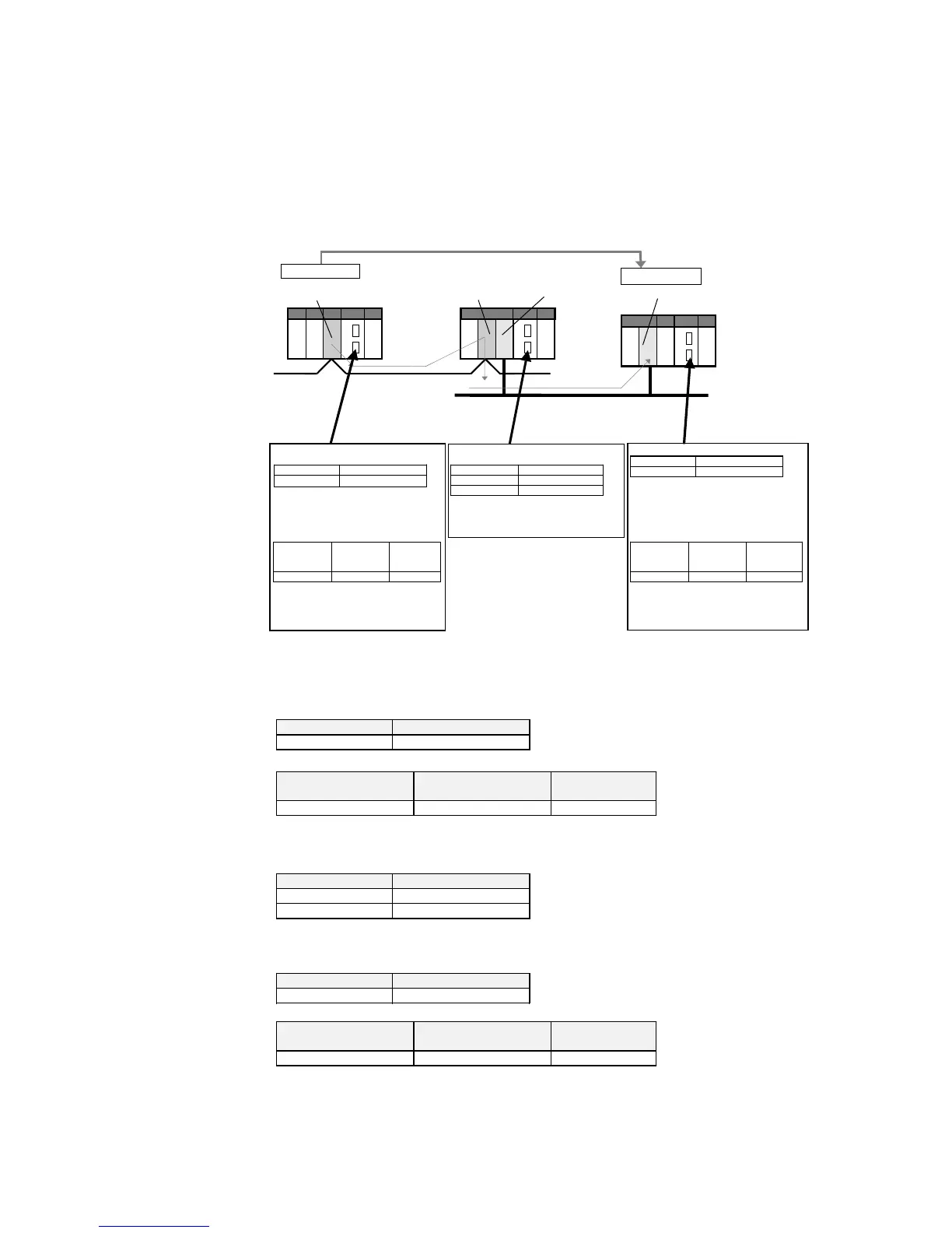
Example: Routing from PLC1 to PLC3
PLC1 Relay Network Table
Destination
network
address
Relay network
address
Relay node
address
2 1 3
To go to network address 2, it is necessary to go
to node address 3 in network address 1.
Node address 1
(Unit number 0)
Node address 3
(Unit number 4)
Relay node PLC2
Network address 1
Node address 1
(Unit number 5)
Target node PLC3
Node address 2 (Unit number 0)
Network address 2
PLC1 Local Network Table
Unit number Local network address
0 1
Go through unit number 0 to send to
network address 1.
PLC2 Local Network Table
Unit number Local network address
4 1
5 2
Go through unit number 5 to send to network
address 2.
Send to node address 2 in
network address 2 to send
to target node.
PLC3 Local Network Table
Unit number Local network address
0 2
Shows that communications frames from
network address 2 go to unit number 0.
PLC3 Relay Network Table
Destination
network
address
Relay network
address
Relay node
address
1 2 1
The communications result must be returned to
PLC1 as a response. To go to network address
1, first it is necessary to go to unit number 0 in
network address 2.
Local node PLC1
Transfer routin
table required in
PLC3.
All of the following routing tables must be created and transferred for this example
network.
PLC1
Local Network Table
Unit number Local network address
0 1
Relay Network Table
Destination network
address
Relay network address Relay node
address
2 1 3
Unit number Local network address
4 1
5 2
Unit number Local network address
0 2
Relay Network Table
Destination network
address
Relay network address Relay node
address
1 2 1
PLC2
Local Network Table
PLC3
Local Network Table
3-9
 Loading...


