6-8 Manual I/O Allocations
6-8-1 I/O Allocation Tab Page
6-8
Manual I/O Allocations
Component - Parameter - Edit - I/O Allocation Tab
Manual I/O allocation is possible with no restrictions on node address order or block
size 1 or 2.
Note: This procedure is the same for the CS1W-DRM21(-V1), CJ1W-DRM21,
CVM1-DRM21-V1, and C200HW-DRM21-V1. In the following setting example, the
CS1W-DRM21(-V1) is used.
6-8-1 I/O Allocation Tab Page
Make the following settings on the I/O Allocation Tab Page.
1. I/O allocation of each OUT/IN memory block (1/2) to the I/O memory area of the
CPU Unit
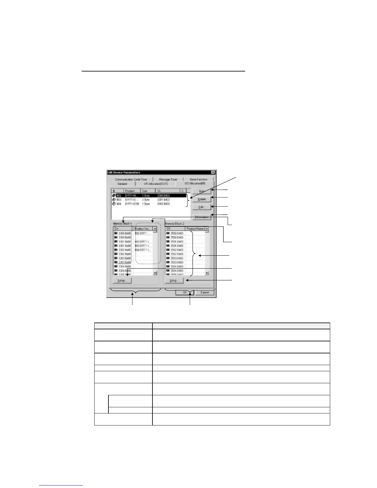
2. Click the I/O Allocation (OUT) or I/O Allocation (IN) Tab. The following dialog box
will be displayed.
Memory block
Product names of allocated slaves
Bytes: Word address and first bit
address
Displays slave information.
Registered Device List
Updates block 2.
Updates block 1.
Block 1 allocations
Automatically allocates I/O to selected slave.
Deletes I/O allocation to selected slave.
Display window to manually edit allocations.
Block 2 allocations
Item Description
Registered Device List Only devices with valid output or input data among all devices registered with
the General Tab Page will be displayed.
Auto Button Allocates in units of words the slaves selected from the Registered Device List
to an unoccupied area in the order of earlier addresses.
Delete Button Unregisters the I/O allocations of the selected slaves in the Registered Device
List.
Edit Button Allows manual allocation through the Edit Window.
Information Button Displays slave information items (i.e., the allocation area and I/O comment
data).
Memory Blocks Displays the allocation status of each slave (product name) of block 1 and block
2.
Ch Bit address where allocation starts. The first bit address will be displayed after
the word address.
Product Name Block 1 and block 2
Setup Button Sets the first address and first address size (i.e., the number of words) of block
1 or block 2.
6-29
 Loading...


