6-8 Manual I/O Allocations
6-8-2 Changing the First Address of Output/Input Block
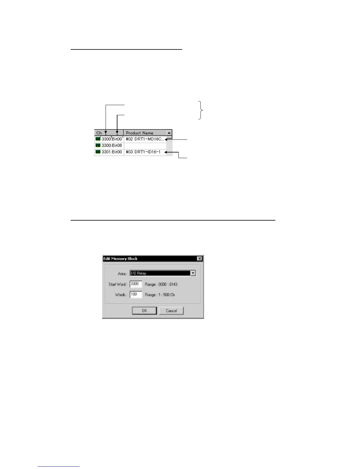
Allocation Status of Blocks 1 and 2
The block allocation status list displays the words of the CPU Unit and the product
names of devices allocated in the respective areas of the CPU Unit.
The start bit and the word address for each device are indicated in the Ch column.
Example:
3300:Bit00: Starts with bit 00 (LSB) of word CIO 3300.
3300:Bit08: Starts with bit 08 (MSB) of word CIO 3300.
Example: Allocation starts with bit 00 (LSB)
of word CIO 3300.
Allocated the bytes beginning with
bit 08 of word CIO 3300.
Therefore, the product name for
3300:Bit08 is left blank.
Product name of slave
First bit address (Bit00)
Word address (Example 3300)
No words in the CPU Unit will be displayed for any memory block that is not in use.
6-8-2 Changing the First Address of Output/Input Block
Component - Parameter - Edit - I/O Allocation Tab - Setup Button
To change the output/input block allocation areas in the I/O memory of the CPU Unit,
use the following procedure.
1. Click the Setup Button of the block to be changed.
2. The following dialog box will be displayed.
6-30
 Loading...


