1-4 PLC Connecting Cables
1-4-1 Direct Serial Connections to a PLC
1-4 PLC Connecting Cables
1-4-1 Direct Serial Connections to a PLC
When connecting the computer running the CX-Integrator directly to a PLC using a serial
line, make the connection correctly using the following Connecting Cables and connection
diagrams.
Connecting Cables to CS/CJ-series PLCs
Unit Unit port Computer
Computer
port
Network type
(serial
communications
mode)
Model Length Remarks
Built-in
peripheral port
IBM PC/AT
or
compatible
D-sub
9-pin male
Peripheral bus
(Toolbus)
or Host Link
(SYSWAY)
CS1W-CN226/626 2 m/6 m ---
Peripheral bus
(Toolbus)
or Host Link
(SYSWAY)
XW2Z-200S-CV/
500S-CV
2 m/5 m Connector
with ESD
(electrostatic
discharge)
countermeasu
res used.
CPU Unit
Built-in
RS-232C port
D-sub 9-pin
male
IBM PC/AT
or
compatible
D-sub
9-pin male
Host Link
(SYSWAY)
XW2Z-200S-V/
500S-V
2 m/5 m ---
XW2Z-200S-CV/
500S-CV
2 m/5 m Connector
with ESD
(electrostatic
discharge)
countermeasu
res used.
Serial
Communications
Boards/Units
RS-232C port
D-sub 9-pin
male
IBM PC/AT
or
compatible
Host Link
(SYSWAY)
XW2Z-200S-V/
500S-V
2 m/5 m -
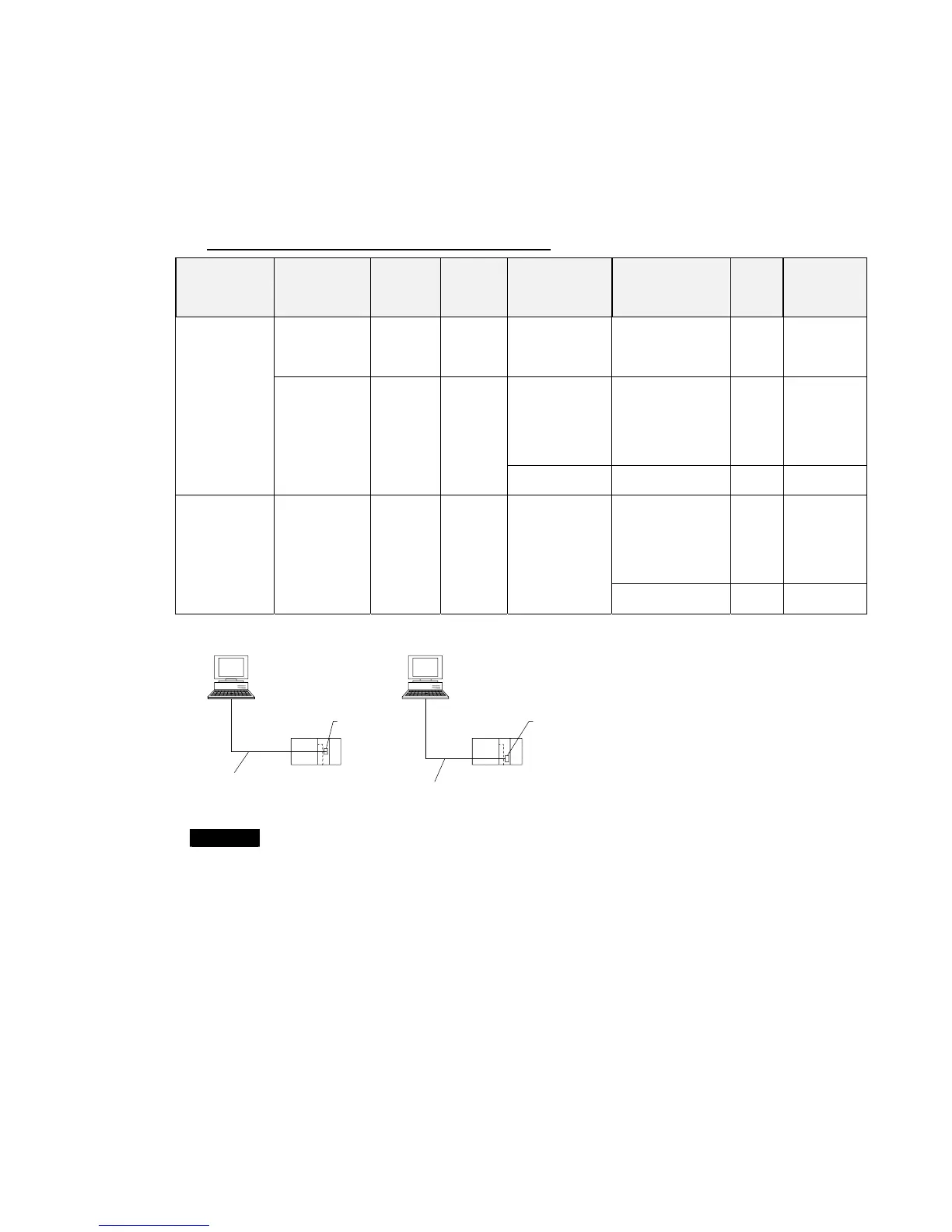
Refer to the following connection diagrams.
Connection to IBM PC/AT or Compatible
Connection to Peripheral Port
IBM PC/AT or compatible
9-pin
CPU Unit peripheral por t
CS1W-CN226 (2.0 m)
CS1W-CN626 (6.0 m)
Connection to RS-232C Port
IBM PC/AT or compatible
9-pin
Built-in RS-232C
por t on CPU Unit
or port on Serial
Communications
Board/Unit
XW2Z-200S-CV (2.0 m)
XW2Z-500S-CV (5.0 m)
9-pin
Note
•When using an RS-232C cable for the computer running CX-Integrator and
connecting to a CS/CJ-series PLC with a Toolbus connection, use a
XW2Z-200S-CV/500S-CV Connecting Cable. (This cable can be used only with IBM
PC/AT or compatible computers.)
•The following connection methods can be used when connecting an RS-232C cable
to a peripheral port on a CS/CJ-series PLC.
1-15
 Loading...


