Installation
36
FQ2 User’s Manual
The X axis in the above optical diagrams represent field of view (mm)
*1
. The Y axis represents the camera
installation distance (mm) or WD (mm). These optical diagrams show the relationship between the detection
range and installation distance for different CCTV Lenses. The values vary for each Lens. Pay close attention
to the Lens that you are using when you refer to these optical diagrams. The macro ring thickness to be used is
given as, for example “t5.0,” on the graphs. “t0” means that a macro ring is not required. “t5.0” means that you
must use a 5-mm macro ring.
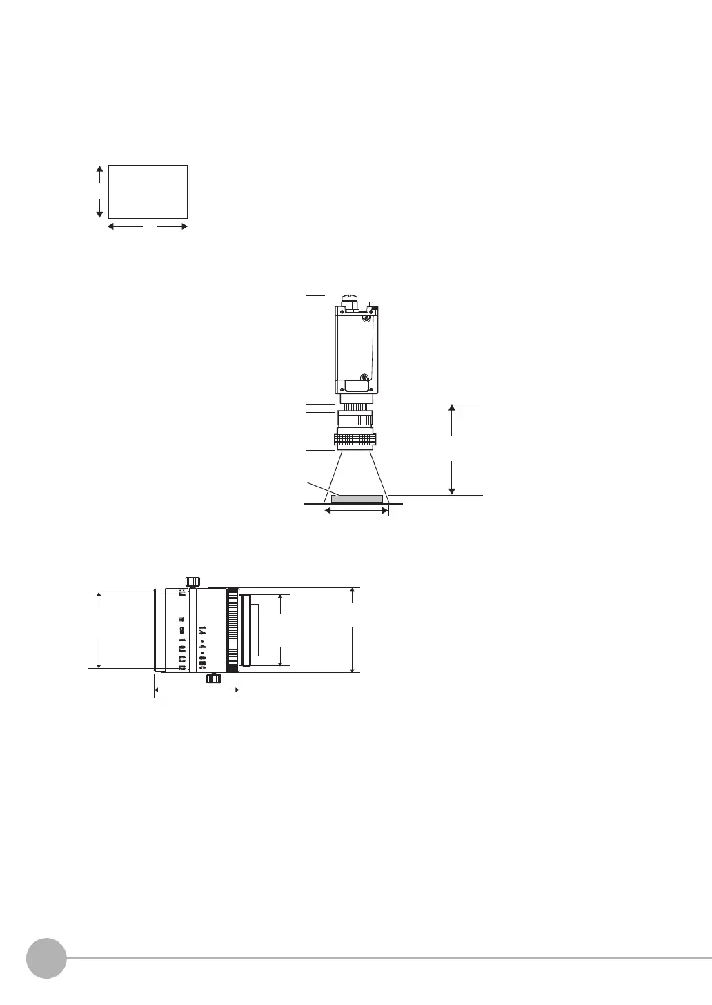
Lens Models and Dimensions
Field of view
Y
X
*1: The Y axis in the optical charts represents the height of the field of view.
Macro ring t@ (mm)
Camera
Camera lens
Measurement object
Camera installation distance (mm)
Field of view (mm)
Example: If you use an 3Z4S-LE SV-2514H Lens for a measurement object that requires field of view of 35
mm, the camera installation distance must be 200 mm and a 2-mm macro ring is required.
Filter threads
1-32 UNF
(C-mount threads)
Maximum outside
diameter
Total length