Part Names and Functions
FQ2 User’s Manual
2
Installation and Connections
31
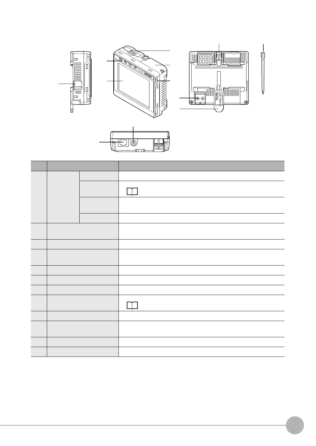
Touch Finder
*1: Applicable to the FQ2-D31 only.
No. Name Description
(1) Operation
indicators
POWER Lights green when the Touch Finder is turned ON.
ERROR Lights red when an error occurs.
11-1 Error Histories p. 398
SD ACCESS Lights yellow when an SD card is inserted.
Flashes yellow when the SD card is being accessed.
CHARGE
*1
Lights orange when the Battery is charging.
(2) LCD/touch panel Displays the setting menu, measurement results, and images input by the
camera.
(3) SD card slot An SD card can be inserted.
(4) Battery cover
*1
The Battery is inserted behind this cover.
Remove the cover when mounting or removing the Battery.
(5) Power supply switch Used to turn the Touch Finder ON and OFF.
(6) Touch pen holder The touch pen can be stored here when it is not being used.
(7) Touch pen Used to operate the touch panel.
(8) DC power supply connector Used to connect a DC power supply.
p. 50
(9) Slider Used to mount the Touch Finder to a DIN Track.
(10) Ethernet port Used when connecting the Touch Finder to the Sensor with an Ethernet
cable. Insert the connector until it locks in place.
(11) Strap holder This is a holder for attaching the strap.
(12) AC power supply connector
*1
Used to connect the AC adapter.
(5)
(1)
(12)
(2)
(6) (7)
(4)
(3)
(11)
(8)
(9)
(10)