2
Installation and Connections
Installation
FQ2 User’s Manual
33
2-3 Installation
Installing the Sensor
FQ2-S@@@@@@ (Sensors with Built-in Lighting)
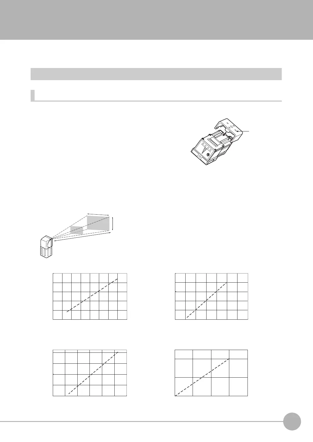
Installation Procedure
1 Align the tabs on one side of the Mounting Bracket with
the slot on the Sensor.
The FQ-XL Mounting Bracket can be attached to the back,
side, or front of the Sensor.
2 Press the Mounting Bracket onto the Sensor until the oth-
er tabs click into place.
3 Use the following optical charts to check the field of view
and installation distance of the Sensor so that it is mount-
ed at the correct position.
Tightening torque (M4): 1.2 N·m
Mounting
Bracket
6
8 10 12 14
0 20 40 60
50
130
210
0100200 300
35
45
55
200
600
1,000
200 400
0
0
400
Horizontal field of view (mm)
Horizontal field of view (mm)
Installation distance (L) (mm)
Installation distance (L) (mm)
FQ2-S@@050F, FQ2-S@@050F
FQ2-S@@100N, FQ2-S@@100N
Horizontal field of view (mm)
Horizontal field of view (mm)
Installation distance (L) (mm)
Installation distance (L) (mm)
FQ2-S@@010F, FQ2-@@010F
FQ2-S@@100F, FQ2-S@@100F
Installation distance (L)
Vertical field
of view
The optical chart indicates the horizontal
field of view. The vertical field of view
depends on the model as follows:
FQ2-S@@@@@@:
Approx. 60% of the horizontal field of view
FQ2-S@@@@@@-08@:
Approx. 90% of the horizontal field of view
Horizontal field of view
Note: The tolerance is ±10%.