Outputting Data and Controlling Operation through EtherNet/IP
300
FQ2 User’s Manual
Setting the Output Format
[In/Out] − [I/O setting] − [Output data setting] − [Link data output]
1 Press [Output format].
2 Press [Output form].
3 Set either a floating point decimal or a fixed decimal for the output form.
Memory Assignments and Commands
Memory Assignments
This section describes the assignments of the command area for the input connection to the Sensor and the
response and output areas for the output connection to the PLC.
● Input Connection to Sensor (PLC Originator to Vision Sensor Target)
• Command Area
Item Description Setting range
Output form
Set the output form for numerical data. Floating point or fixed point (default: Floating
point)
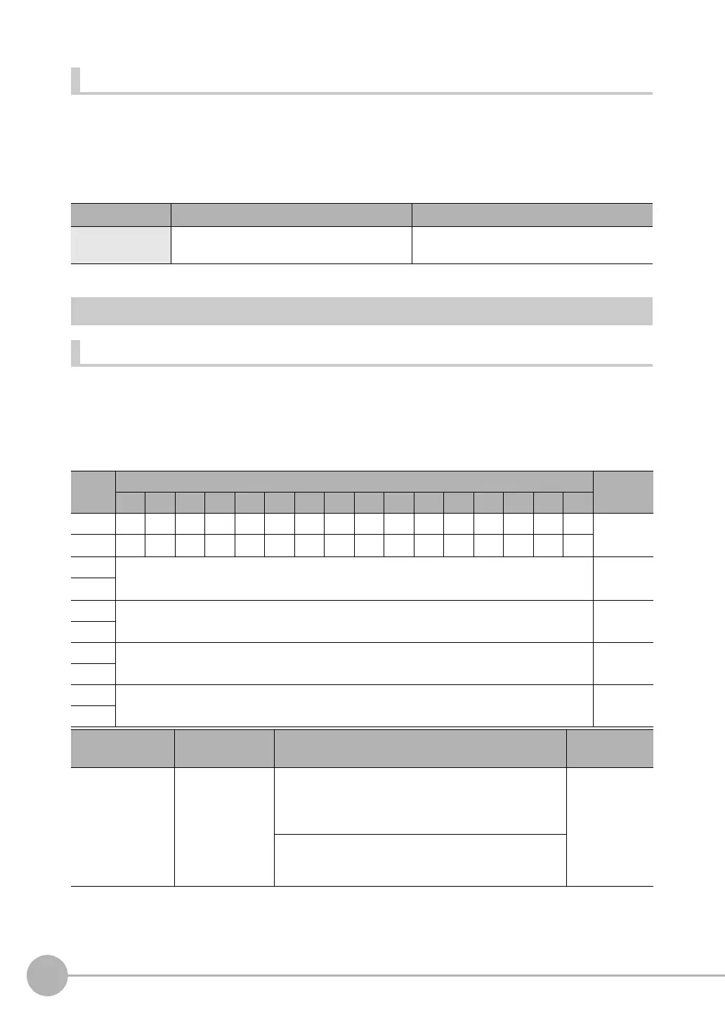
Bits Contents
15 14 13 12 11 10 9 8 7 6 5 4 3 2 1 0
+0
ERCLR
Resv Resv Resv Resv Resv Resv Resv Resv Resv Resv Resv Resv Resv TRIG EXE Control sig-
nals (32
bits)
+1 Resv Resv Resv Resv Resv Resv Resv Resv Resv Resv Resv Resv Resv Resv Resv DSA
+2 Command code Command
code (32
bits)
+3
+4 Parameter 1 Parameter 1
(32 bits)
+5
+6 Parameter 2 Parameter 2
(32 bits)
+7
+8 Parameter 3 Parameter 3
(32 bits)
+9
Signal Signal name Function Application
method
EXE Control Command
Execution Bit
Turn ON this signal from the PLC to send a control com-
mand for the Vision Sensor to execute.
Set the control command code and parameters before
you turn ON this signal.
Command/
response com-
munications
Turn OFF the EXE signal from the PLC when the Control
Command Completed (FLG) signal from the Vision Sen-
sor turns ON.