FQ2-series Vision Sensors
20
FQ2 User’s Manual
1-1 FQ2-series Vision Sensors
The FQ2 Series features Vision Sensors with integrated cameras and controllers. They can be used to easily
achieve simple inspections and measurements.
You can use parallel controls, no-protocol communications on Ethernet, PLC Link communications on Ethernet,
and EtherNet/IP communications on Ethernet as standard features. You can also use a Data Unit to enable
control with full-scale parallel communications or RS-232C communications.
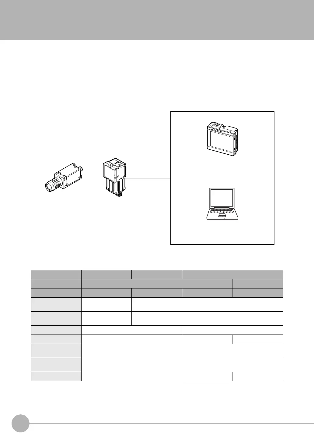
To set up and monitor the Vision Sensor, you can use either the Touch Finder or the PC Tool running on a
computer. For actual operation, you can use the Vision Sensor on a stand-alone basis.
FQ2-series Vision Sensors are available in two different models. There are also Sensors with C-mounts that
allow you to change the lens, and Sensors with Built-in Lighting. The differences are given in the following
table.
Models Single-function models Standard models High-resolution models
Typ e Sensors with Built-in Lighting Sensors with C-mounts
Model number FQ2-S1@@@@@ FQ2-S2@@@@@ FQ2-S3@@@@@-08@ FQ2-S3@-13@
Number of simultaneous
measurements
132
Number of registered
scenes
832
Partial input Horizontally only Horizontally and vertically
Lens mount --- C-mount
Image processing
method
Real color Real color or monochrome (Model numbers for
Monochrome Sensors end in “M.”)
Connection to Sensor
Data Unit
Not possible. Possible.
Processing resolution 752×480 928×828 1280×1024
The same functions as those that are
provided by the Touch Finder can be
performed from a computer. The PC Tool
is available free of charge.
After the Sensor has been set up, it can be
operated alone to perform measurements
without the Touch Finder or PC Tool.
PC Tool
Used to check images and set the
judgement parameters. It can also be
used to save measurement results and
check status during operation.
FQ2 Vision Sensor
Touch Finder
Setup, Image Confirmation, and Logging Tools
Sensor with C-mount
Sensor with
Built-in Lighting