Installation
34
FQ2 User’s Manual
• There is a certain amount of deviation among Sensors in the center of the optical axis. For this reason, when install-
ing the Sensor, check the center of the image and the field of view on the LCD monitor of the Touch Finder and in
the PC Tool.
Removal Procedure
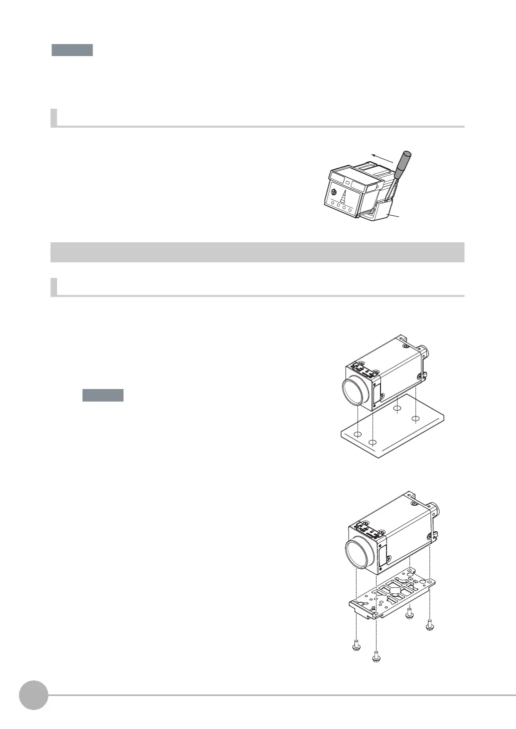
FQ2-S3@-@@@ (Sensors with C-mounts)
Installation Procedure
Directly Mounting the Sensor
Mounting the Sensor to the Base
1 Insert a flat-blade screwdriver between the Mounting Brack-
et and the Sensor case on either side and remove the
Mounting Bracket.
1 Mount the Sensor with M3 screws.
Tightening torque: 0.54 N·m
Effective depth of mounting holes: 4 mm
Refer to the dimension drawings in the appendix for the positions of
the screw holes.
1 You can attach the mounting base to the bottom, top, left,
or right surface.
(Recommended mounting screw tightening torque:
0.54 N·m)
Tightening torque: 0.54 N·m
Effective depth of mounting holes: 4 mm
2 Mount the Sensor with M3 screws.
Tightening torque: 0.54 N·m
Effective depth of mounting holes: 4 mm
Important