Wiring
FQ2 User’s Manual
2
Installation and Connections
45
FQ-SDU10/SDU15 Terminal Signal Names
*1: Leave all signal terminals that are labeled “NC” open.
*2: You can select whether to turn the external lighting ON (Positive) or OFF (Negative) when the signal turns ON. (The setting is called the
strobe output polarity.)
Changing the Output Timing and Output Time of the STGOUT Signal: p. 270
*3: This control signal is used to turn ON external lighting when an image is taken. Connect this signal to external lighting.
*4: This signal is output to an external device when exposure of the imaging elements is completed. If you want to move the Sensor to the next
measurement location after a measurement is completed, move the Sensor only after this signal turns ON.
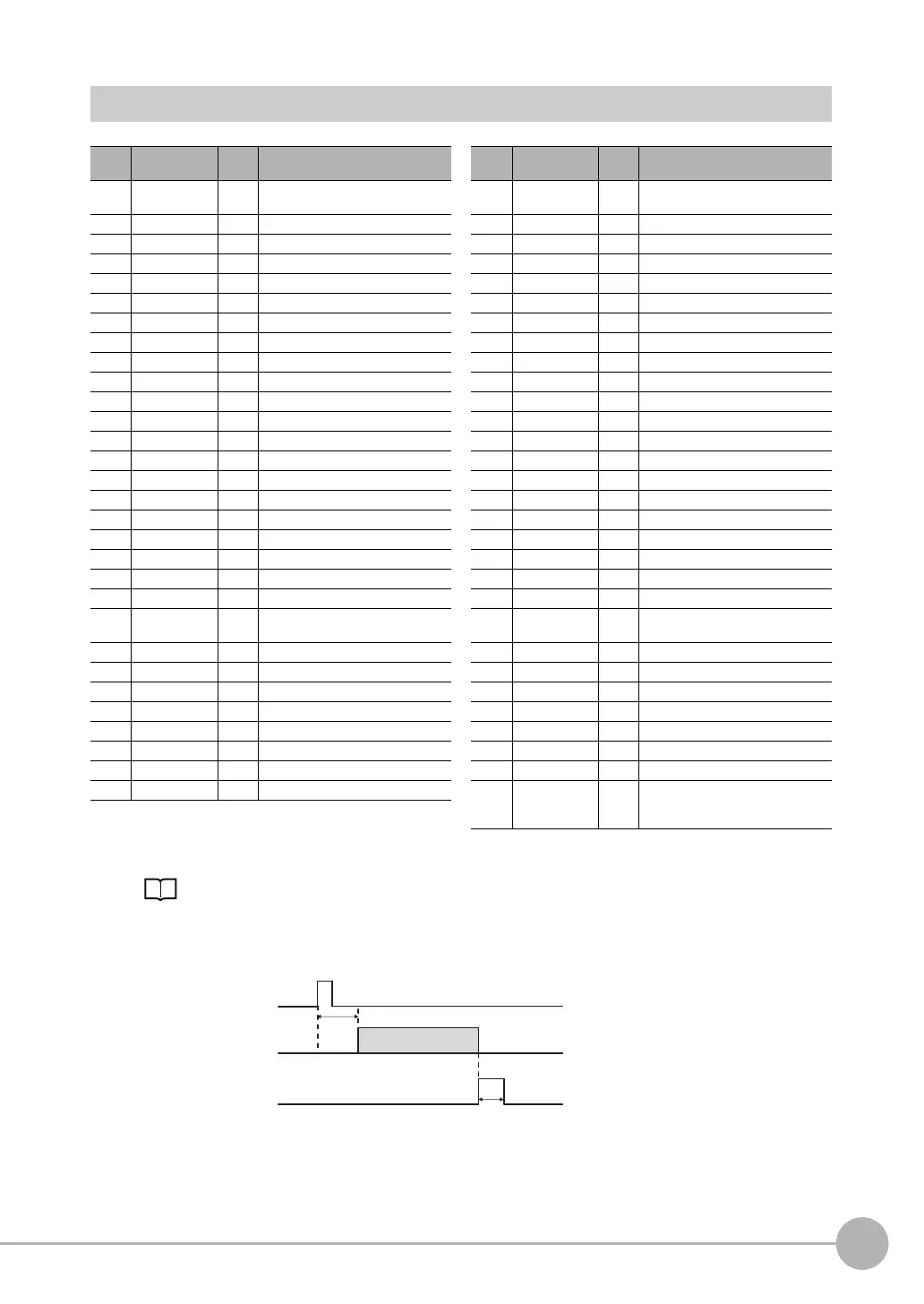
Shutter Output Signal (SHTOUT)
Pin Signal IN/
OUT
Function Pin Signal IN/
OUT
Function
1 COMOUT1 - Output signal common (DO0 to
DO15)
31 COMIN0 - Input signal common (all inputs
except TRIG)
2NC
*1
- 32 COMIN1 - Input signal common (TRIG)
3 D0 OUT Data output 33 TRIG IN Measurement trigger input
4 D1 OUT Data output 34 NC
*1
-
5 D2 OUT Data output 35 NC
*1
-
6 D3 OUT Data output 36 RESET IN Reset input
7 D4 OUT Data output 37 IN0 IN Command input
8 D5 OUT Data output 38 IN1 IN Command input
9 D6 OUT Data output 39 IN2 IN Command input
10 D7 OUT Data output 40 IN3 IN Command input
11 D8 OUT Data output 41 IN4 IN Command input
12 D9 OUT Data output 42 IN5 IN Command input
13 D10 OUT Data output 43 IN6 IN Command input
14 D11 OUT Data output 44 IN7 IN Command input
15 D12 OUT Data output 45 NC
*1
-
16 D13 OUT Data output 46 NC
*1
-
17 D14 OUT Data output 47 DSA IN Data send request signal
18 D15 OUT Data output 48 NC
*1
-
19 NC
*1
-49NC
*1
-
20 NC
*1
-50NC
*1
-
21 NC
*1
-51NC
*1
-
22 NC
*1
- 52 ACK OUT Command execution completed
flag
23 NC
*1
- 53 RUN OUT ON during measurement mode
24 NC
*1
- 54 BUSY OUT ON during process execution
25 NC
*1
- 55 OR OUT Overall judgement result
26 NC
*1
- 56 ERROR OUT ON during error
27 NC
*1
- 57 STGOUT OUT Strobe trigger output
*2, *3
28 NC
*1
- 58 SHTOUT OUT Shutter trigger output
*4
29 NC
*1
- 59 GATE OUT ON during the set output time.
30 NC
*1
- 60 COMOUT0 - Output signal common (ACK,
RUN, BUSY, OR, ERROR,
STGOUT, SHTOUT, and GATE)
Trigger input (TRIG)
Shutter time
Imaging element
shutter signal
SHTOUT
10 ms
Trigger delay
ON
OFF
ON
OFF
ON
OFF
The SHTOUT signal turns ON for approximately 10 ms (fixed) when the shutter time (exposure period) elapses after
the trigger is input from an external device.