Adjustment Suggestions
4-11
Adjustment Suggestions
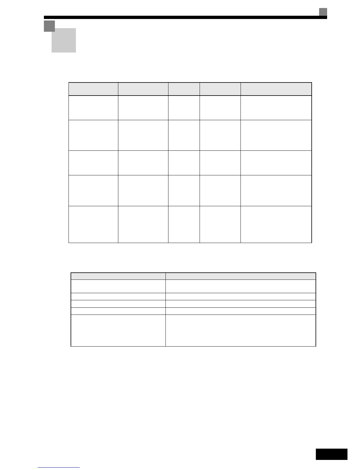
If hunting, vibration or other problems occur during trial operation, adjust the parameters listed in the follow-
ing table according to the control method. This table lists the most commonly used user parameters only.
The following user parameters will also affect the control system indirectly.
Table 4.4 Useful Parameters in case of Problems during Trial Operation
Name (Parameter
Number)
Performance
Factory Set-
ting
Recommended
Setting
Adjustment Method
Hunting-prevention
gain (N1-02)
Controlling hunting and
vibration in middle-
range speeds
(20 to 80% FMAX)
1.00 0.50 to 2.00
• Reduce the setting if torque is
insufficient for heavy loads.
• Increase the setting if hunting or
vibration occurs for light loads.
Carrier frequency selec-
tion
(C6-02)
• Reducing motor mag-
netic noise
• Controlling hunting
and vibration at low
speeds
Depends on
capacity
0.4 kHz to
default
• Increase the setting if motor
magnetic noise is high.
• Reduce the setting if hunting or
vibration occurs at low to mid-
dle-range speeds.
Torque compensation
delay time constant
(C4-02)
• Increasing torque and
speed response
• Controlling hunting
and vibration
Depends on
capacity
200 to 1000 ms
• Reduce the setting if torque or
speed response is slow.
• Increase the setting if hunting or
vibration occurs.
Torque compensation
gain (C4-01)
• Improving torque at
low speeds (10 Hz or
lower)
• Controlling hunting
and vibration
1.00 0.50 to 1.50
• Increase the setting in small
steps of 0.05 if torque is insuffi-
cient at low speeds.
• Reduce the setting if hunting or
vibration occurs for light loads.
Middle output fre-
quency voltage
(E1-08)
Minimum output fre-
quency voltage
(E1-10)
• Improving torque at
low speeds
• Controlling shock at
startup
Depends on
capacity and
voltage
Default to
“Default + 3 to 5
V”
*1
*1. The setting is given for 200 V Class Inverters. Double the voltage for 400 V Class Inverters.
• Increase the setting in small
steps of 1 or 2 V if torque is
insufficient at low speeds
• Reduce the setting if shock at
startup is large.
Table 4.5 Parameters influencing performance indirectly
Name (Parameter Number) Application
Acceleration/deceleration times
(C1-01 to C1-09)
Adjust torque during acceleration and deceleration.
S-curve characteristics (C2-01 and C2-02) Used to prevent speed shock at start or stop of the acceleration.
Jump frequencies (d3-01 to d3-04) Used to avoid resonance points during constant speed.
Analog input filter time constant (H3-12) Used to prevent fluctuations in analog input signals caused by noise.
Stall prevention (L3-01 to L3-06)
Used to prevent OV (overvoltage error) and motor stalling for heavy
loads or rapid acceleration/deceleration. Stall prevention is enabled by
default and the setting normally has not to be changed. When using an
optional braking resistor unit and braking unit, however, disable stall pre-
vention during deceleration by setting L3-04 to 0.