Wiring Control Circuit Terminals
2-31
Control Circuit Terminal Functions
The functions of the control circuit terminals are shown in Table 2.14.
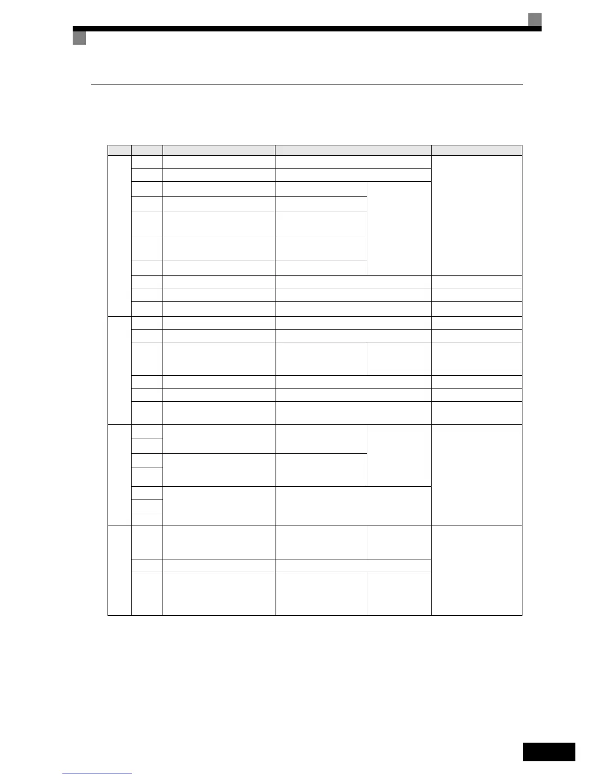
Table 2.14 Control Circuit Terminals with Default Settings
Type No. Signal Name Function Signal Level
Digital input signals
S1 Forward run/stop command Forward run when ON; stopped when OFF.
24 VDC, 8 mA
Photocoupler isolation
S2 Reverse run/stop command Reverse run when ON; stopped when OFF.
S3
External fault input
*1
Fault when ON.
Functions are
selected by set-
ting H1-01 to
H1-05.
S4
Fault reset
*1
Reset when ON
S5
Multi-step speed reference 1
*1
(Master/auxiliary switch)
Auxiliary frequency ref-
erence when ON.
S6
Multi-step speed reference 2
*1
Multi-step speed 2 when
ON.
S7
Jog frequency reference
*1
Jog frequency when ON.
SC Digital input common – –
SN Digital Input Neutral – –
SP Digital Input Power Supply +24VDC power supply for digital inputs
24 VDC, 250 mA max.
*2
Analog input signals
+V 15 V power output 15 V power supply for analog references 15 V (Max. curr.: 20mA)
A1 Frequency reference 0 to +10 V/100% 0 to +10 V (20 kΩ)
A2 Auxiliary Frequency Reference
Auxiliary analog fre-
quency reference;
4 to 20 mA (250Ω)
Function is
selected by set-
ting H3-09.
4 to 20 mA (250Ω)
0 V to +10 V (20kΩ)
0 to 20 mA (250Ω)
-V -15 V power output -15 V power supply for analog references
AC Analog reference common – –
E(G)
Shield wire, optional ground
line connection point
––
Digital output signals
M1
During run
(1NO contact)
Closed during Run
Function selected
by H2-01 and
H2-02
Relay contacts
Contact capacity:
1 A max. at 250 VAC
1 A max. at 30 VDC
*3
M2
M3
Zero speed
(1NO contact)
CLOSED when output
frequency at zero level
(b2-01) or below
M4
MA
Fault output signal
CLOSED across MA and MC during faults
OPEN across MB and MC during faults
MB
MC
analog output
signals
FM Output frequency
Analog output frequency
signal;
0 to 10 V; 10V=FMAX
Function selected
by H4-01
0 to +10 V max. ±5%
2 mA max.
AC Analog common –
AM Inverter output power
Analog output power sig-
nal;
0 to 10V; 10V=max.
appl. motor capacity
Function selected
by H4-04