Wiring Control Circuit Terminals
2-27
Wiring Control Circuit Terminals
Wire Sizes
For remote operation using analog signals, keep the control line length between the Analog Operator or oper-
ation signals and the Inverter to 50 m or less, and separate the lines from main power lines or other control cir-
cuits to reduce induction from peripheral devices.
When setting frequencies from an external frequency source (and not from a Digital Operator), use shielded
twisted-pair wires and ground the shield for the largest area of contact between shield and ground.
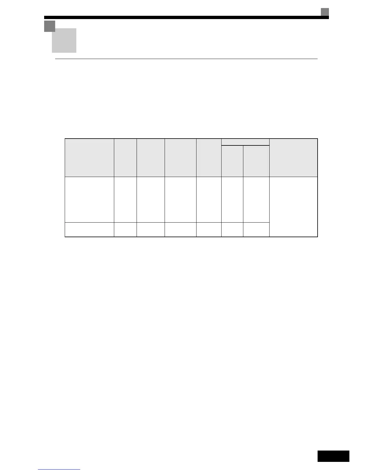
Terminal numbers and wire sizes are shown in Table 2.12.
Table 2.12 Terminal Numbers and Wire Sizes (Same for all models)
Terminals
Termi-
nal
Screws
Tighten-
ing Torque
(N•m)
Possible
Wire
Sizes
mm
2
(AWG)
Recom-
mended
Wire Size
mm
2
(AWG)
IP54 Inverters Only
Wire Type
Cable
Gland
Size
Possible
Clamping
Cable
Diam.
(mm)
FM, AC, AM, SC, SP,
SN, A1, A2, +V, -V,
S1, S2, S3, S4,
S5, S6, S7
MA, MB, MC, M1,
M2, M3, M4,
R+, R-, S+, S-, IG
Phoenix
type
0.5 to 0.6
Single wire
*1
:
0.14 to 2.5
Stranded
wire:
0.14 to 1.5
(26 to 14)
*1. We recommend using cable-end sleeves on signal lines to simplify wiring and to improve reliability.
0.75
(18)
M25
*2
*2. Refer to Table 2.5 for tightening torques for the cable glands.
9 to 17
• Shielded, twisted-
pair wire
*3
• Shielded, polyeth-
ylene-covered,
vinyl sheath cable
*3. Use shielded twisted-pair cables to input an external frequency reference.
E (G) M3.5 0.8 to 1.0
0.5 to 2
(20 to 14)
1.25
(12)
--