Terminal Block Configuration
2-5
Terminal Block Configuration
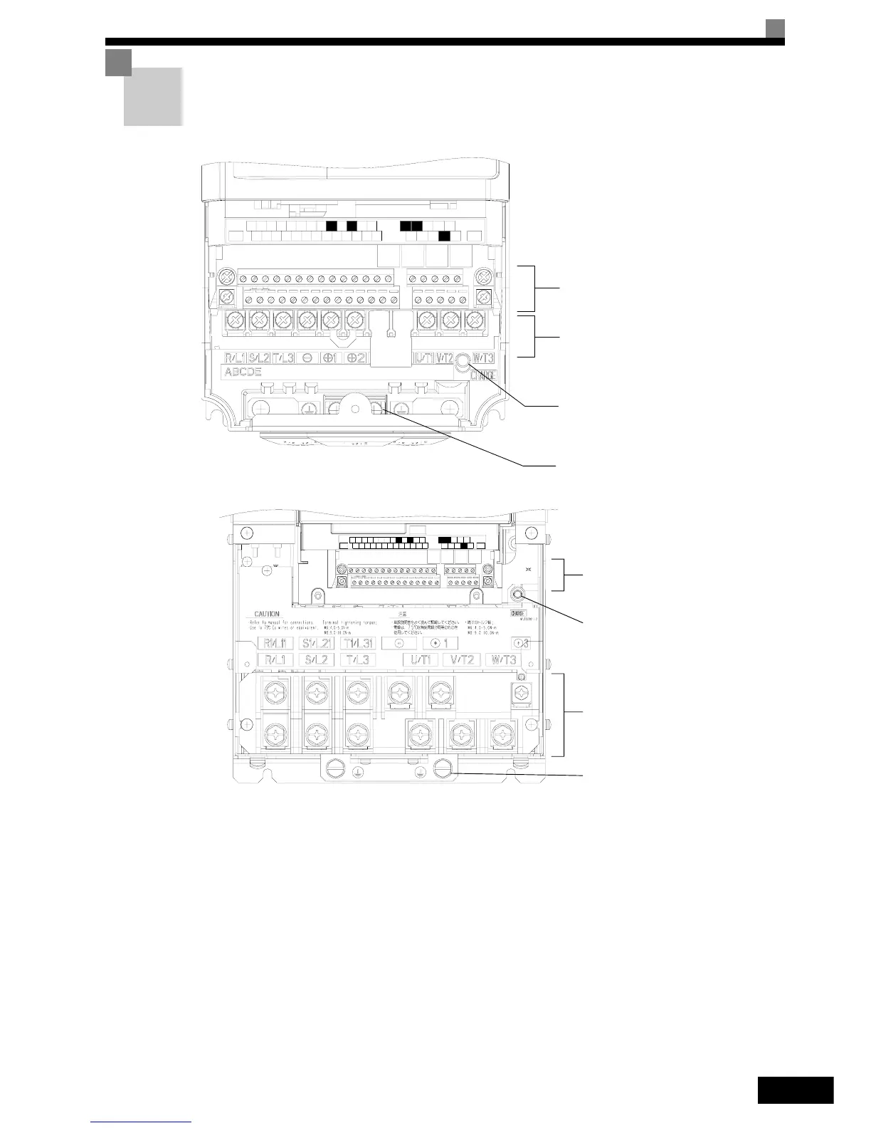
The terminal arrangements are shown in Fig 2.3 and Fig 2.4.
Fig 2.3 Terminal Arrangement (200V / 400V Class Inverter of 0.4 kW)
Fig 2.4 Terminal Arrangement (200V / 400V Class Inverter of 22 kW or more)
AC
ACS6
-V
A
M
R+
M5
RPAC
S1 S4
SP
S7
M4
+V
S3
SC
IG
A2
M2
SN M6
F
M
A1
E(G)
E(G
)
M
CMB
S5
M1
M
P
MA
M3
S2 S+
R-
S-
N
O
TU
S
ED
Control Circuit Terminals
Main Circuit Terminals
Charge Indicator
Ground Terminal
AC
ACS6
-V
AM
R+
M5
RPAC
S1 S4
SP
S7 M4
+V
S3
SC
IG
A2
M2
SN
M6
FM
A1
E(G)
E(G)
MCMB
S5 M1
MP
MA
M3S2 S+
R-
S-
Control Circuit Terminals
Carge Indicator
Main Circuit Terminals
Ground Terminals