6-72
• Beside MEMOBUS the drive is also capable of using Metasys N2 communications via the RS485/422
port. Setting parameter H5-08 to 0 activates MEMOBUS communication, setting 1 enables Metasys N2.
Note: A additional manual for the Metasys N2 protocol is available on request.
• The setting of parameter H5-09 determines the length of time that serial communications must be lost
before a CE fault occurs.
Setting Precautions
• If the Inverter trips with CE faults with a communication speed setting of 19200 bps, lower the communi-
cation speed.
• If the Inverter trips with CE faults with lower communication speed selections lengthen the send wait time
in parameter H5-06
• If the Inverter’s station address is set to 0 it will ignore all messages from the master.
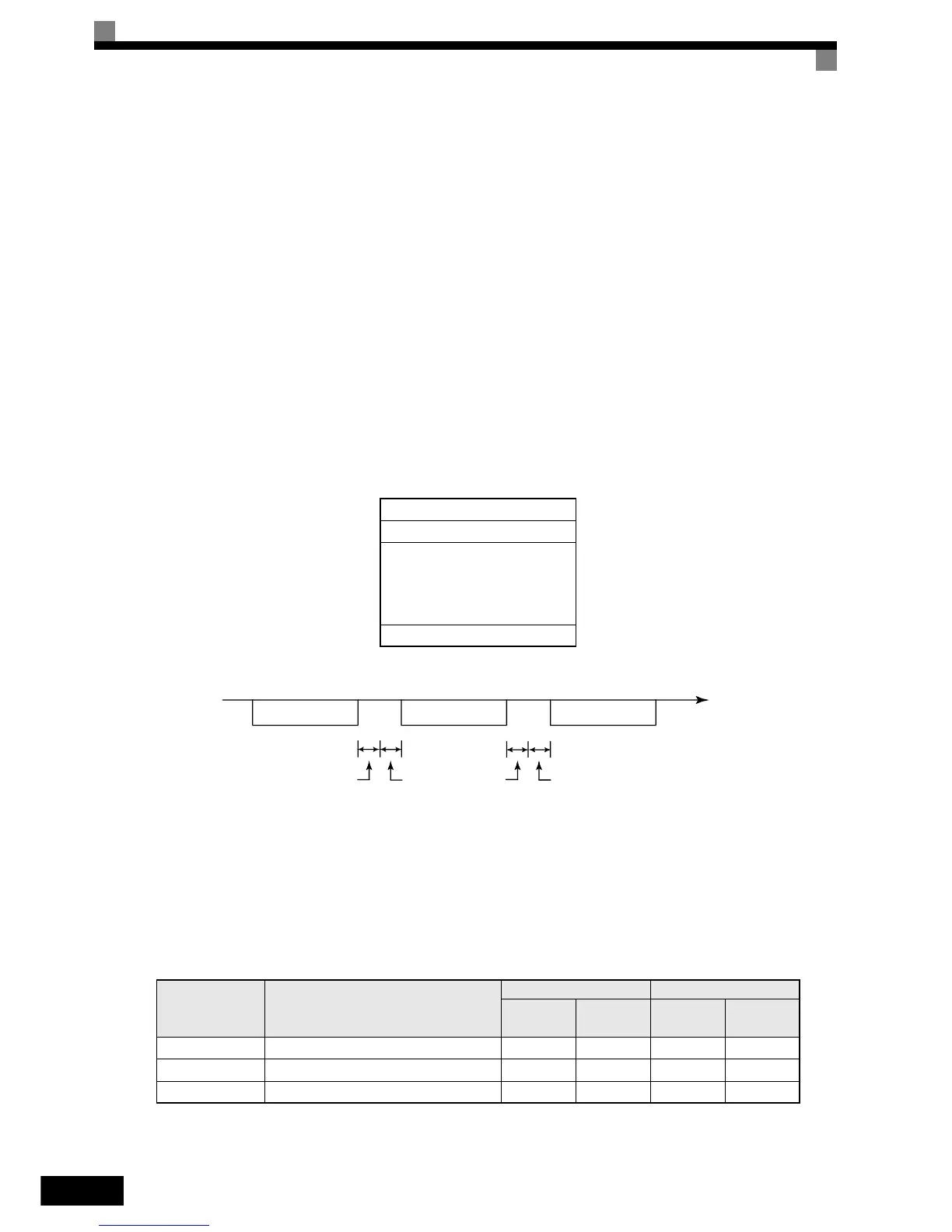
Message Format
In MEMOBUS communication the master sends commands to the slave and the slave responds. The message
format is configured for both sending and receiving as shown below and the length of data packets depends on
the command (function) content.
The space between messages must meet the following conditions:
Fig 6.53 Message Spacing
Slave Address
Set the address from 0 to 32. If set to 0, commands from the master will be received by all slaves. (Refer to
“Broadcast Data” on the following pages.)
Function Code
The function code specifies commands. The three function codes shown in the table below are available.
Slave address
Function code
Data
Error check
Function Code
(Hexadecimal)
Function
Command Message Response Message
Min. (Bytes) Max. (Bytes) Min. (Bytes) Max. (Bytes)
03H Read memory register contents 8 8 7 37
08H Loopback test 8 8 8 8
10H Write multiple memory registers 11 41 8 8
PLC to Inverter
Inverter to PLC
PLC to Inverter
Command message
Response message
Command message
Time
24 bits long
5 ms min.
H5-06
setting
24 bits long