6-64
Output Terminal Functions
The digital multifunction outputs can be set for several functions using the H2-01 and H2-02 parameters (ter-
minal M1 to M4 function selection). These functions are described in the following section.
Related Parameters
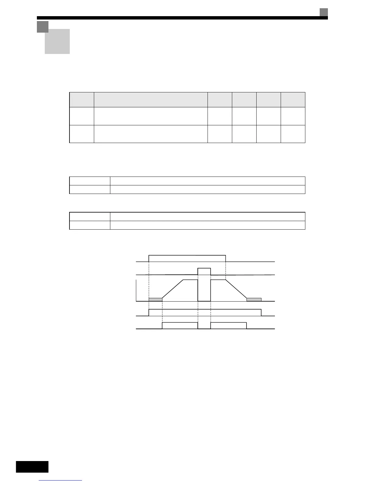
During Run (Setting: 0) and During Run 2 (Setting: 37)
During Run (Setting: 0)
During Run 2 (Setting: 37)
These outputs can be used to indicate the Inverter’s operating status.
Fig 6.47 Timing Chart for During Run and During Run 2 Output
Parameter
Number
Name
Setting
Range
Factory
Setting
Change
during
Operation
Access
Level
H2-01 Terminal M1-M2 function selection 0 to 3D 0 No A
H2-02 Terminal M3-M4 function selection 0 to 3D 1 No A
OFF The RUN command is OFF, the Inverter output is OFF
ON The RUN command is ON, the Inverter output is giving out a voltage.
OFF The Inverter does not give out a frequency. (During baseblock, DC injection or stopped)
ON The Inverter gives out a frequency.
OFF
ON
OFF
OFF
OFF
ON
ON
ON
Run command
Baseblock command
Output frequency
During run 1 output
During run 2 output