Acceleration and Deceleration Characteristics
6-15
Acceleration and Deceleration Characteristics
This section explains the acceleration and deceleration characteristics of the Inverter.
Setting Acceleration and Deceleration Times
Acceleration time indicates the time to increase the output frequency from 0% to 100% of the maximum out-
put frequency (E1-04). Deceleration time indicates the time to decrease the output frequency from 100% to
0% of (E1-04). The accel./decel. times 1 are used with the factory setting, the accel./decel. times 2 can be
selected using a multifunction input.
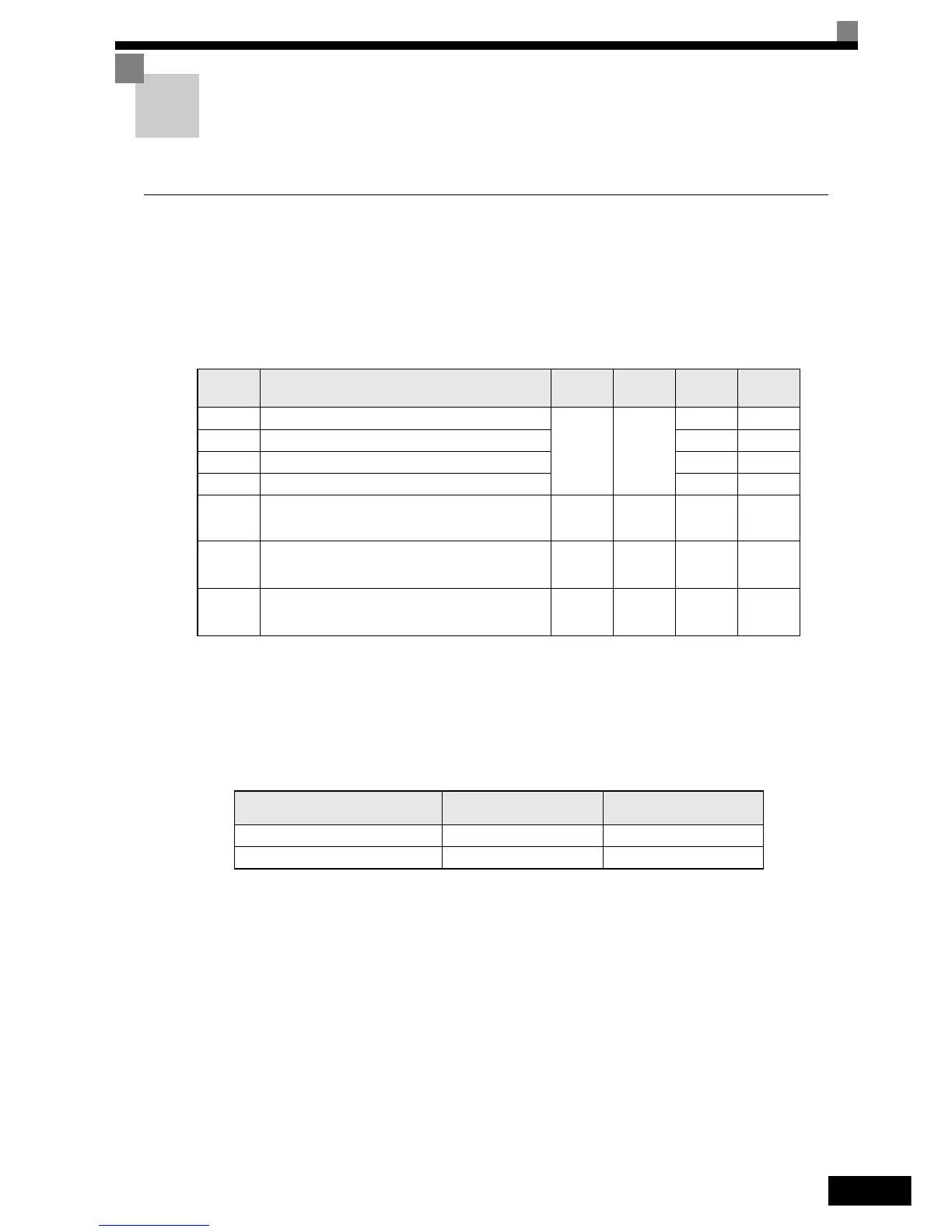
Related Parameters
Switching Acceleration and Deceleration Time Using Multi-Function Input Terminal
Commands
Two different acceleration times and deceleration times can be set. When one multi-function input terminal
(H1-) is set to 7 (acceleration/deceleration time selection 1), the acceleration/deceleration time can even
be switched during operation by changing the ON/OFF status of this terminal.
The following table shows the acceleration/deceleration time switching combinations.
Switching Acceleration and Deceleration Time Automatically
Use this setting when the acceleration/deceleration time should be switched automatically depending on the
output frequency.
When the output frequency reaches the set value in C1-11, the Inverter switches the acceleration/deceleration
time automatically as shown in the following diagram.
Parameter
Number
Name
Setting
Range
Factory
Setting
Change
during
Operation
Access
Level
C1-01 Acceleration time 1
0.0 to
6000.0
10.0 sec.
Yes Q
C1-02 Deceleration time 1 Yes Q
C1-03 Acceleration time 2 Yes A
C1-04 Deceleration time 2 Yes A
C1-11 Acceleration/deceleration time switching frequency
0.0 to
200.0
0.0 Hz No A
C2-01 S-curve characteristic time at acceleration start
0.00 to
2.50
0.20 sec. No A
C2-02 S-curve characteristic time at acceleration end
0.00 to
2.50
0.20 sec. No A
Acceleration/Deceleration Time
Selection 1 Terminal
Acceleration Time Deceleration Time
OFF C1-01 C1-02
ON C1-03 C1-04