2-4
Circuit Descriptions
Refer to the numbers indicated in Fig 2.1 and Fig 2.2.
1 These circuits are hazardous and are separated from accessible surfaces by protective separation.
2 These circuits are separated from all other circuits by protective separation consisting of double and
reinforced insulation. These circuits may be interconnected with SELV (or equivalent) or non-
SELV
*
circuits, but not both.
3 Inverter supplied by four-wire-system source (neutral grounded)
These circuits are SELV
*
circuits and are separated from all other circuits by protective separation
consisting of double and reinforced insulation. These circuits may only be interconnected with
other SELV
*
(or equivalent) circuits.
Inverter supplied by three-wire-system source (ungrounded or corner grounded)
These circuits are not separated from hazardous circuits by protective separation, but only with
basic insulation. These circuits must not be interconnected with any circuits which are accessible,
unless they are isolated from accessible circuits by supplemental insulation.
* SELV (Safety Extra Low Voltage) circuits have no direct connection to the primary power and are supplied
by a transformer or equivalent isolating device. The circuits are designed and protected, so that, under normal
and fault condition, its voltage does not exceed a safe value. (See IEC 61010)
IMPORTANT
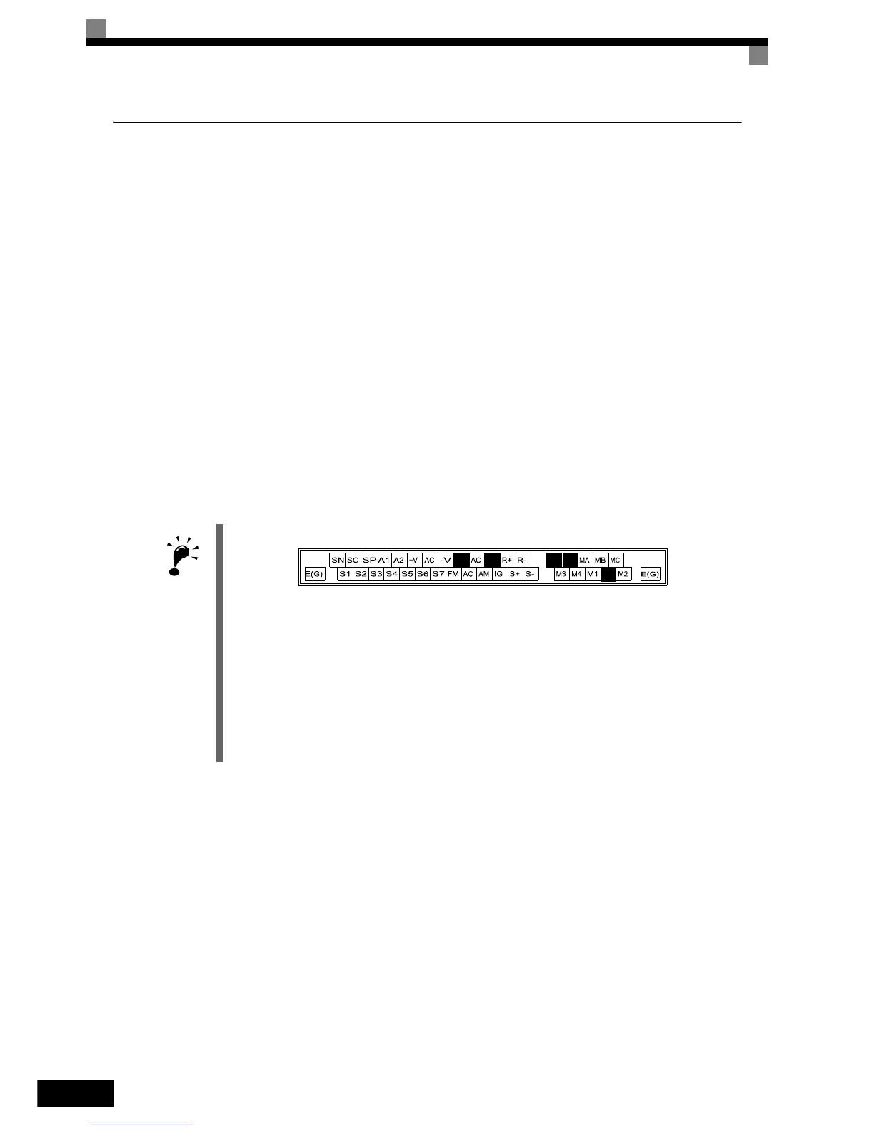
1. Control circuit terminals are arranged as shown below.
2. The output current capability of the +V terminal is 20 mA.
3. Main circuit terminals are indicated with double circles and control circuit terminals are indicated with single cir-
cles.
4. The wiring of the digital inputs S1 to S7 is shown for the connection of relay contacts or NPN transistors (0V com-
mon and sinking mode). This is the default setting.
For the connection of PNP transistors or for using a 24V external power supply, refer to page 2-33, Sinking/Sourc-
ing Mode.
5. The master speed frequency reference can be input either at terminal A1 or at terminal A2 by changing the setting
of parameter H3-13. The default setting is terminal A2.
6. DC reactors to improve the input power factor are built into 200 V Class Inverters from 22 up to 110 kW and 400
V Class Inverters from 22 up to 300 kW. A DC reactor is an option only for Inverters of 18.5 kW or less. Remove
the short circuit bar when connecting a DC reactor.