1-6
Component Names
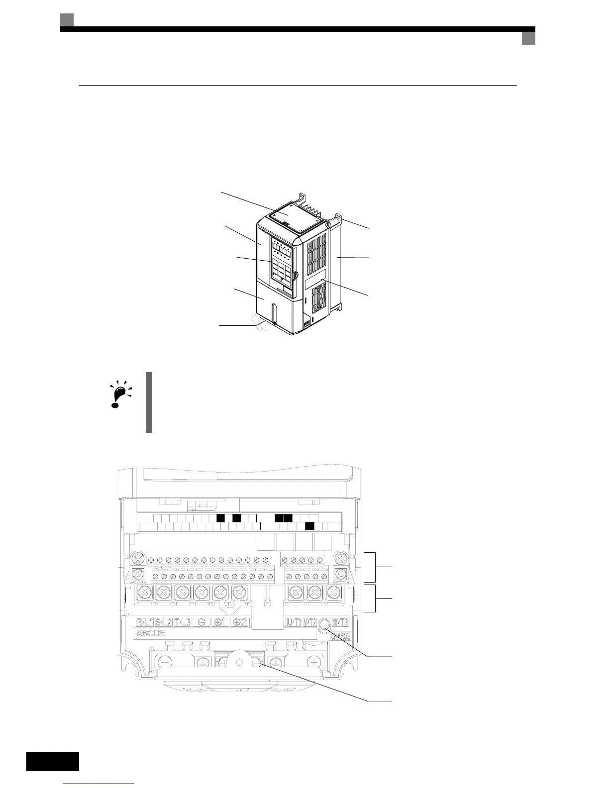
Inverters of 18.5 kW or Less
The external appearance and component names of the Inverter are shown in Fig 1.4, the terminal arrangement
in Fig 1.5
Fig 1.4 NEMA 1 Inverter Appearance (18.5 kW or Less)
Fig 1.5 Terminal Arrangement (18.5 kW or less)
IMPORTANT
The top cover is a protection against foreign bodies (screws, metal scrap from drilling etc.), which could fall
into the inverter during the installation in the cabinet.
Remove the top cover when the installation is finished!
Top cover
Front cover
Digital Operator
Terminal cover
Bottom protective cover
Diecast case
Nameplate
Mounting hole
AC
AC
S6
-V
AM
R+
M5
RPAC
S1 S4
SP
S7 M4
+V
S3
SC
IG
A2
M2
SN M6
FM
A1
E(G)
E(G)
MCMB
S5 M1
MP
MA
M3S2
S+
R-
S-
N
O
TU
S
ED
Control Circuit Terminals
Main Circuit Terminals
Charge Indicator
Ground Terminal