Confirmations upon Delivery
1-7
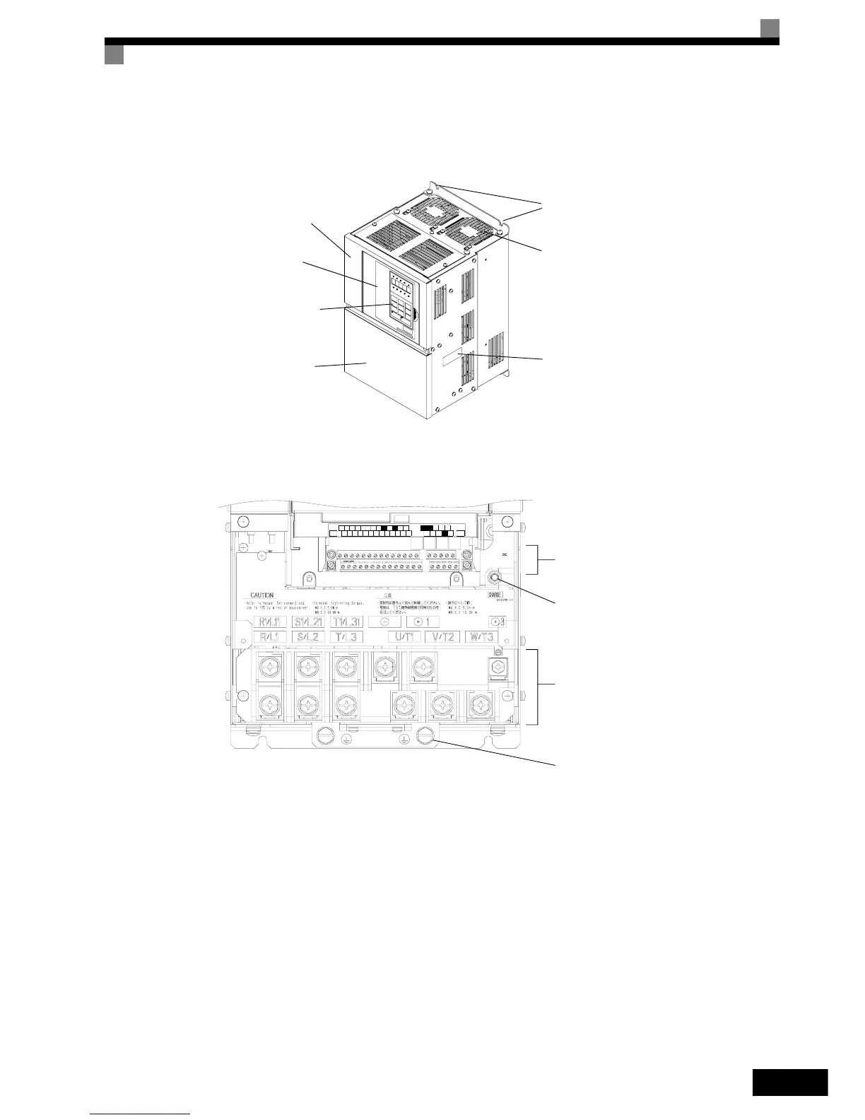
Inverters of 22 kW or More
The external appearance and component names of the Inverter are shown in Fig 1.6, the terminal arrangement
in Fig 1.7
Fig 1.6 Inverter Appearance (22 kW or More)
Fig 1.7 Terminal Arrangement (22kW or More)
Mounting holes
Cooling fan
Nameplate
Inverter cover
Front cover
Digital Operator
Terminal cover
AC
ACS6
-V
AM
R+
M5
RPAC
S1 S4
SP
S7 M4
+V
S3
SC
IG
A2
M2
SN
M6
FM
A1
E(G)
E(G)
MCMB
S5 M1
MP
MA
M3S2 S+
R-
S-
Control Circuit Terminals
Carge Indicator
Main Circuit Terminals
Ground Terminals