Monitor Parameters
6-67
Monitor Parameters
This section explains the analog monitor and pulse monitor parameters.
Using the Analog Monitor Parameters
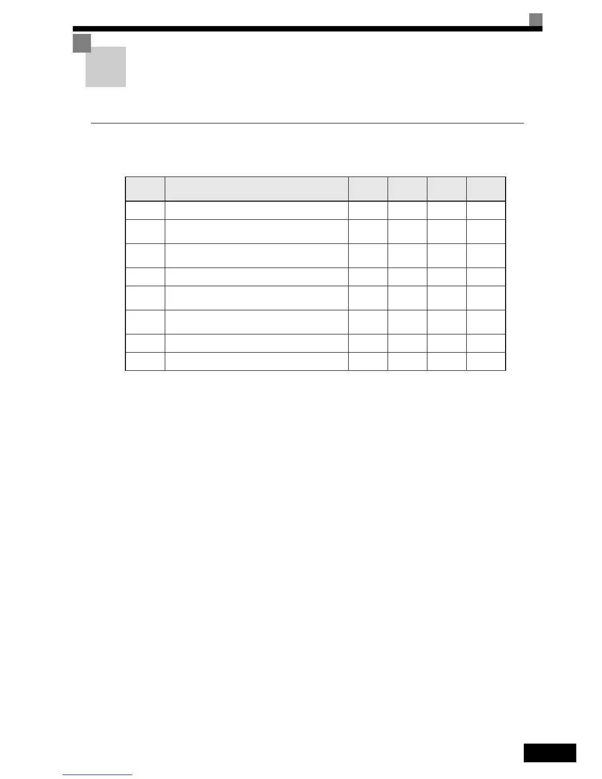
Related Parameters
Selecting Analog Monitor Items
Some of the Digital Operator monitor items (U1- [status monitors]) can be output at the multi-function
analog output terminals FM-AC and AM-AC. Refer to page 5-41, Monitor Parameters: U, and set the param-
eter number of U1 group (
part of U1-) for the parameters H4-01 respectively H4-04.
Adjusting the Analog Monitor Items
Adjust the output voltage for multi-function analog output terminals FM-AC and AM-AC using the gain and
bias in H4-02, H4-03, H4-05, and H4-06.
The gain sets the analog output voltage value which is equal to 100% of the monitor item.
The bias sets the analog output voltage value which is equal to 0% of the monitor item.
Note that the maximum output voltage is 10V. A voltage higher than this value can not be output.
Selecting the Signal Level
Select the signal level for the analog outputs using parameters H4-07 and H4-08. The default setting is 0 to
10V. If a current output signal of 4 to 20mA should be used an optional terminal board (ETC618121) with
additional analog current outputs is required.
Parameter
Number
Name
Setting
Range
Factory
Setting
Change
during
Operation
Access
Level
H4-01 Terminal FM monitor selection 1 to 38 2 No A
H4-02 Terminal FM gain
0 ~
1000.0%
100% Yes A
H4-03 Terminal FM bias
-110.0 ~
+110.0%
0.0% Yes A
H4-04 Terminal AM monitor selection 1 to 53 8 No A
H4-05 Terminal AM gain
0 ~
1000.0%
50% Yes A
H4-06 Terminal AM bias
-110.0 ~
+110.0%
0.0% Yes A
H4-07 Terminal FM signal level selection
0 or 2
*1
*1. An analog output signal of 4-20 mA (setting 2) requires an optional terminal board (ETC618121) for current output.
0NoA
H4-08 Terminal AM signal level selection
0 or 2
*1
0NoA