7-8
Alarm Detection
Alarms are detected as a type of Inverter protection function that do not operate the fault relay output. The sys-
tem will automatically return to its original status when the cause of the alarm has been removed.
The Digital Operator display and the Alarm LED flashes and the alarm can be output at the multi-function out-
puts (H2-01 or H2-02). As long as the Inverter remains in Alarm status it can not be started and will not accept
parameter changes.
When an alarm occurs, take appropriate countermeasures according to the table below.
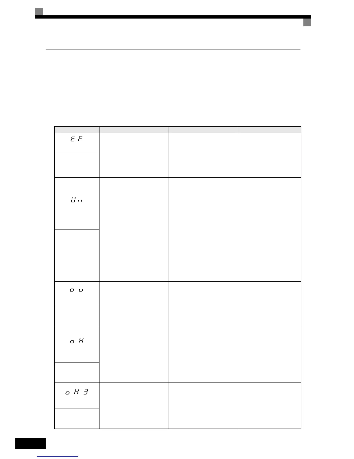
Table 7.2 Alarm Content
Display Meaning Probable Causes Corrective Actions
(flashing)
Forward/Reverse Run Com-
mands Input Together
Both the forward and the reverse
run commands are input simulta-
neously for 500 msec or more.
This alarm will decelerate the
motor stop
The external forward and reverse
command were input simulta-
neously.
Check external sequence
logic, so only one input is
received at a time.
EF
External Fault
(flashing)
(flashing)
DC Bus Undervoltage
The DC bus voltage is below the
Undervoltage Detection Level
(L2-05). The default settings are:
200 V class: 190 VDC
400 V class: 380 VDC
The MC of the inrush current pre-
vention circuit opened.
The control power supply voltage
was below the CUV level.
• The voltage fluctuations of the
power supply are too high.
• A momentary power loss has
occurred.
• The terminal screws of the
input power supply are loose.
• An open-phase error occurred
at the input terminals.
• The acceleration time is set too
short.
• A fault occurred in the inrush
current prevention circuit.
• An external load at the control
terminals was pulling down the
Inverter’s power supplies or
there was an internal short in
the power/gate drive board.
• Check the input voltage.
• Check the wiring of the
input terminals.
• In case of Main Circuit MC
Operation Failure replace
the Inverter.
• Remove all connections to
the control terminals and
cycle the power to the
Inverter.
• Replace the Inverter.
UV
DC Bus Undervolt
(flashing)
(flashing)
DC Bus Overvoltage
The DC bus voltage exceeded the
overvoltage detection level.
Refer to
page 6-100 for the OV
detection level.
OV Alarm is only detected when
the drive is in a stopped condition
The power supply voltage is too
high.
Check the power supply and
decrease the voltage to meet
the Inverter’s specifications
OV
DC Bus Overvolt
(flashing)
(flashing)
Heatsink Overheat Alarm
The temperature of the Inverter's
cooling fin exceeded the setting
in L8-02 while L8-03 = 3
• The ambient temperature is too
high.
• There is a heat source nearby.
• The Inverter cooling fan(s) has
stopped.
• Check for dirt build-up on
the fans or heatsink.
• Install a cooling unit.
• Remove the heat source.
OH
Heatsnk Overtmp
(flashing)
(flashing)
Motor Overheat Alarm
Detected when the level at A2,
programmed for motor tempera-
ture (thermistor input, H3-09=E),
exceeds 1.17 V for the time L1-
05 and L1-03 = 3
Overheating of the motor has
been measured by the motor ther-
mistor.
• Check for dirt build-up on
the fans or heatsink.
• Install a cooling unit.
• Remove the heat source.
OH3
Motor Overheat 1
(flashing)