6-100
Setting the V/f Pattern
Using the E1- parameters the Inverter input voltage and the V/f pattern can be set as needed. It is not rec-
ommended to change the settings when the motor is used in open loop vector control mode.
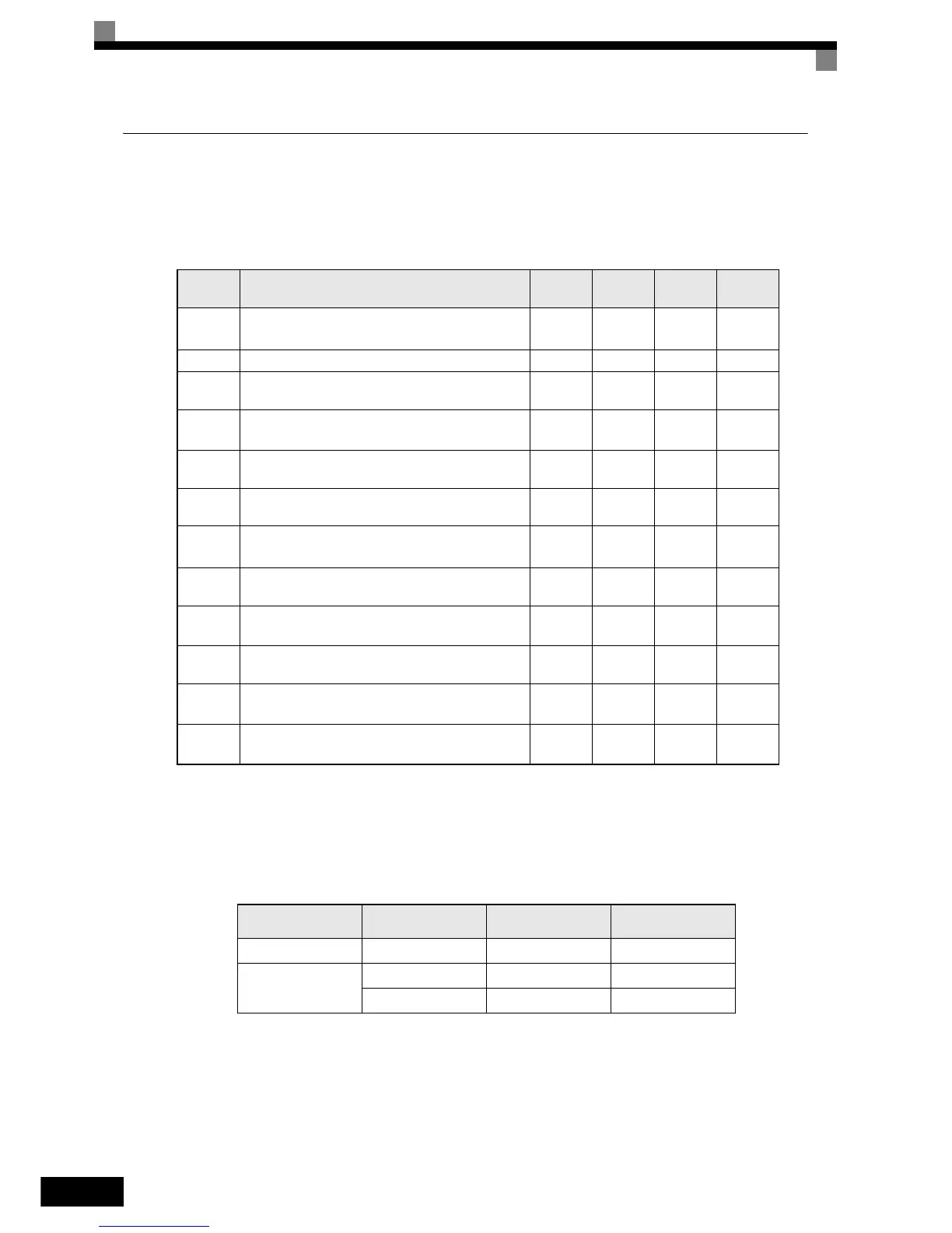
Related Parameters
Setting Inverter Input Voltage
Set the Inverter input voltage correctly in E1-01 so that it matches the power supply voltage. The set value
becomes a reference value for the stall prevention during deceleration and the overvoltage level according to
the table below.
Setting V/f Pattern
The V/f pattern can be selected using parameter E1-03. There are two methods of setting the V/f pattern:
Select one of the 15 preset pattern types (set value: 0 to E), or set a user-defined V/f pattern (set value: F).
The factory setting for E1-03 is F.
To select one of the existing patterns, refer to the following table.
Parameter
Number
Name
Setting
Range
Factory
Setting
Change
during
Operation
Access
Level
E1-01 Input voltage setting
155 to
255
*1
*1. Values for 200 V class Inverters are shown. For a 400 V class Inverter the values have to be doubled.
200 V
*1
No Q
E1-03 V/f pattern selection 0 to F, FF F No A
E1-04 Max. output frequency (FMAX)
0.0 to
200.0
50.0 Hz No A
E1-05 Max. output voltage (VMAX)
0.0 to
255.0
*1
200.0 V
*1
No A
E1-06 Base frequency (FA)
0.0 to
200.0
50.0 Hz No A
E1-07 Mid. output frequency (FB)
0.0 to
200.0
2.5 Hz No A
E1-08 Mid. output frequency voltage (VB)
0.0 to
255
*1
15.0 V
*1
No A
E1-09 Min. output frequency (FMIN)
0.0 to
200.0
1.2 Hz No A
E1-10 Min. output frequency voltage (VMIN)
0.0 to
255.0
*1
9.0 V
*1
No A
E1-11 Mid. output frequency 2
0.0 to
200.0
0.0 Hz
*2
*2. Parameters E1-11 and E1-12 are disabled when set to 0.0
No A
E1-12 Mid. output frequency voltage 2
0.0 to
255.0
*1
0.0 V
*2
No A
E1-13 Base voltage (VBASE)
0.0 to
255.0
*1
0.0 V No A
Inverter
Voltage Class
Input Voltage
Setting E1-01
OV Level
Stall Prevention
during Decel Level
200 V 200 V 410 VDC 377 VDC
400 V
O 400 V 720 VDC 662 VDC
P 400 V 820 VDC 754 VDC