Output Terminal Functions
6-65
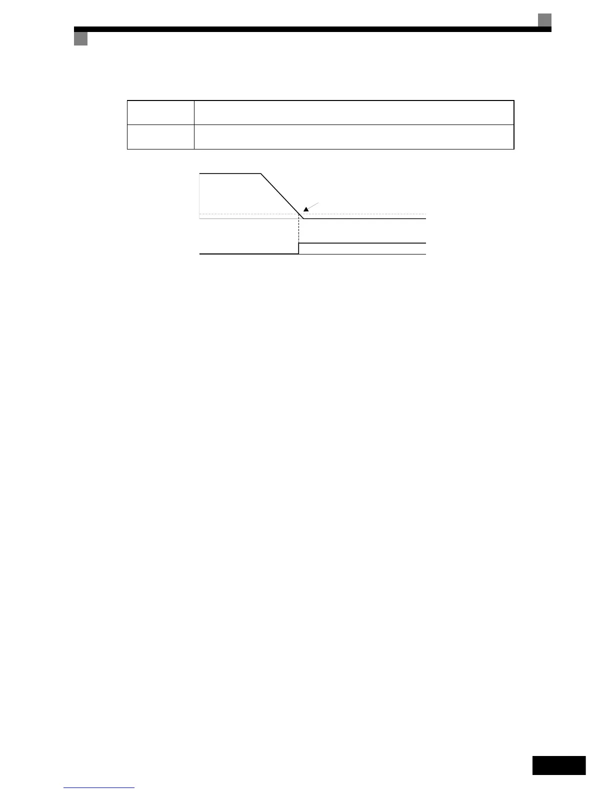
Zero Speed (Setting: 1)
Fig 6.48 Timing Chart for Zero-speed
Inverter Operation Ready (Setting: 6)
If a multi-function digital output is programmed to 6 the output will be switched ON when the initialisation of
the Inverter at startup has finished without any faults.
During DC Bus Undervoltage (Setting: 7)
If a multi-function digital output is programmed to 7 the output is switched ON as long as a DC bus undervolt-
age is detected.
During Baseblock (Setting: 8)
If a multi-function digital output is programmed to 8 the output is switched ON as long as the Inverter output
is base blocked.
Frequency Reference Source Selection (Setting: 9)
If a multi-function digital output is programmed to 9 the output is ON when the Digital Operator is selected as
frequency reference source. If any other frequency reference is selected the output is switched OFF.
Run Command Source Selection Status (Setting: A)
If a multi-function digital output is programmed to A the output is switched ON when the digital operator is
selected as RUN command source. If any other RUN command source is selected output is switched OFF.
Fault (Setting: E)
If a multi-function digital output is programmed to E the output is switched ON when any fault different from
CPF00 and CPF01 occurs. The output is also not switched in alarm condition. (Refer to Chapter 7, Trouble-
shooting for fault and alarm lists.)
Minor Fault (Alarm) (Setting: 10)
If a multi-function digital output is programmed to 10 the output is switched ON when the Inverter is in alarm
condition (refer to page 7-8, Alarm Detection pp.).
OFF
The output frequency is higher than the zero speed level (DC injection braking start level,
b2-01).
ON
The output frequency is lower than the zero speed level (DC injection braking start level,
b2-01).
Zero speed level (b2-01)
OFF
ON
Zero-speed output
Output frequency