2-32
Fig 2.18 Flywheel Diode Connection
Switch S1 - Standard Terminal Board
The Switch S1 can be used to terminate the internal RS422/485 port and for selecting the input signal type for
analog input A2. See Fig 2.19 for details.
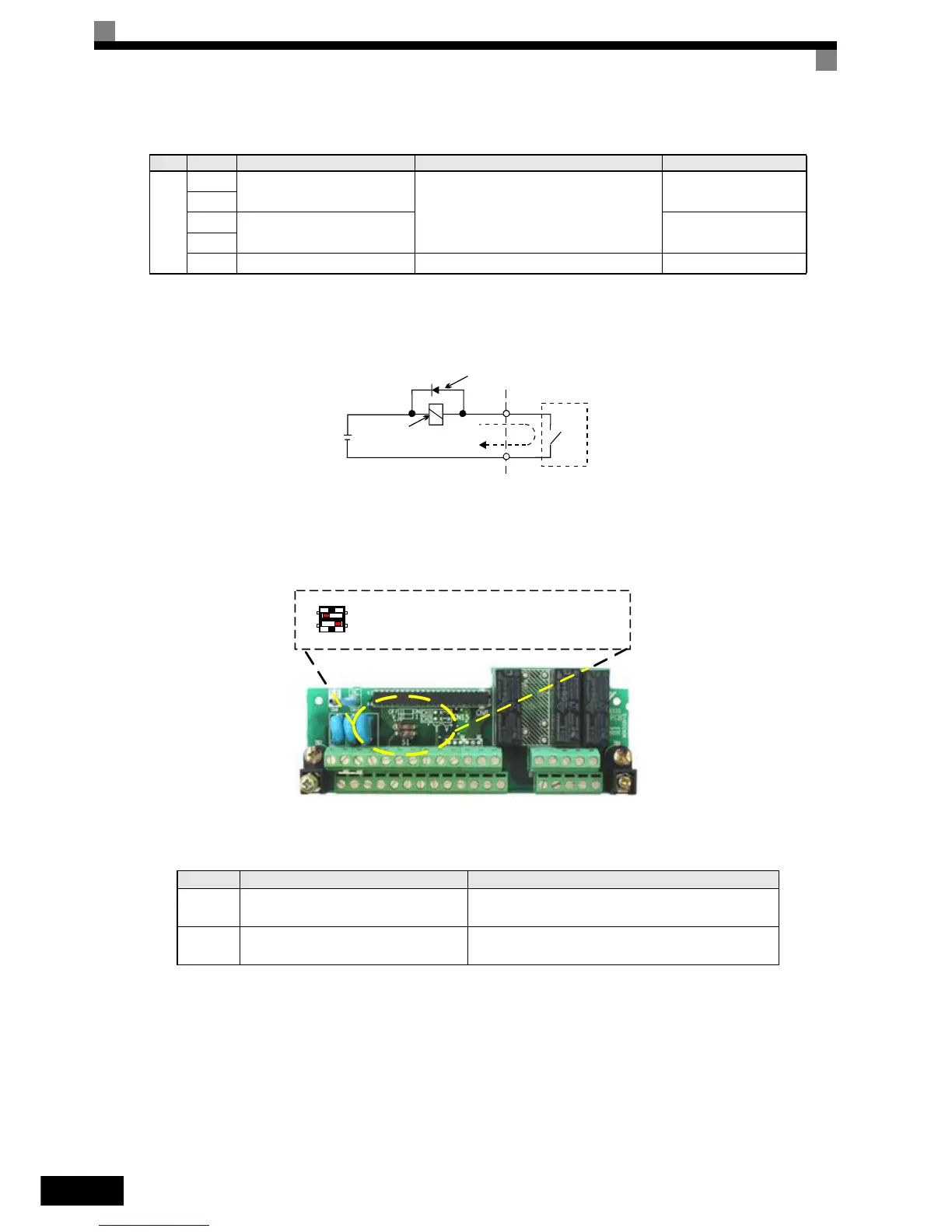
Fig 2.19 Standard terminal board - Switch S1 function
The settings of switch S1 is shown in the following table.
RS-485/
422
R+
MEMOBUS communications
input
For 2-wire RS-485, short R+ and S+ as well
as R- and S-.
Differential input, PHC
isolation
R-
S+
MEMOBUS communications
output
Differential input, PHC
isolation
S-
IG Signal common – –
*1. The default settings are given for terminals S3 to S7. For a 3-wire sequence, the default settings are a 3-wire sequence for S5, multi-step speed setting
1 for S6 and multi-step speed setting 2 for S7.
*2. Do not use this power supply for supplying any external equipment.
*3. When driving a reactive load, such as a relay coil with DC power supply, always insert a flywheel diode as shown in
Fig 2.18
Name Function Setting
S1-1
RS-485 and RS-422 terminating resis-
tance
OFF: No terminating resistance
ON: Terminating resistance of 110 Ω
S1-2 Input method for analog input A2
V: 0 to 10 V (internal resistance: 20 kΩ)
I: 4 to 20 mA (internal resistance: 250 Ω)
Table 2.14 Control Circuit Terminals with Default Settings
Type No. Signal Name Function Signal Level
External power:
30 VDC max.
Coil
Flywheel diode
1 A max.
The rating of the flywheel diode
must be at least as high as the cir-
cuit voltage.
RS422/485 Port Termination Resistance
Analog Input A2 Current/Voltage Signal Selection
S1
Off On
V I