6-8
Connection Example and Time Chart
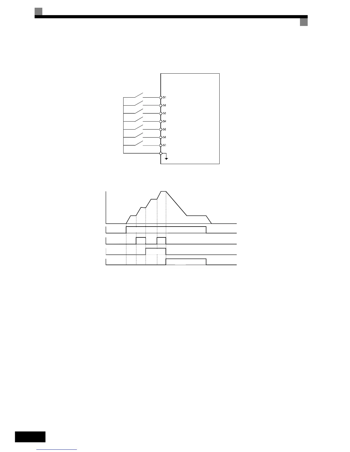
The following diagram shows a time chart and control circuit terminal connection example during a 9-step
operation.
Fig 6.9 Control Circuit Terminal During 5-step Operation
Fig 6.10 Multi-step speed command/Jog Frequency Selection Time Chart
Note:
• The multifunction input setting “Jog Frequency 2” (69) can be used for jog frequency selection when a
3-wire control is used for the control circuit. If it is selected while the inverter is initialized to 2-wire con-
trol an OPE03 alarm will be displayed.
Inverter
Forward/stop
Reverse/stop
Fault reset
Multi-step command 1
Multi-step command 2
Jog frequency
External fault
Digital input neutral
SN
Forward/stop
Multi-step speed
command 1
Multi-step speed
command 2
Jog frequency selection
Frequency
reference 3
Frequency
reference 4
Jog frequency
Frequency
reference
Frequency
reference 2
Frequency
reference 1
ON
ON
ON
ON
OFF
OFF
OFF
OFF