6-10
Performing Operations Using 3-Wire Control
When any parameter from H1-01 to H1-05 (multi-function digital input terminals S3 to S7) is set to 0, termi-
nals S1 and S2 are used for a 3-wire control, and the multi-function input terminal that has been set to 0 works
as a forward/reverse selection command terminal.
When the Inverter is initialized for 3-wire control with A1-03, multi-function input 3 becomes the input termi-
nal for the forward/reverse run command.
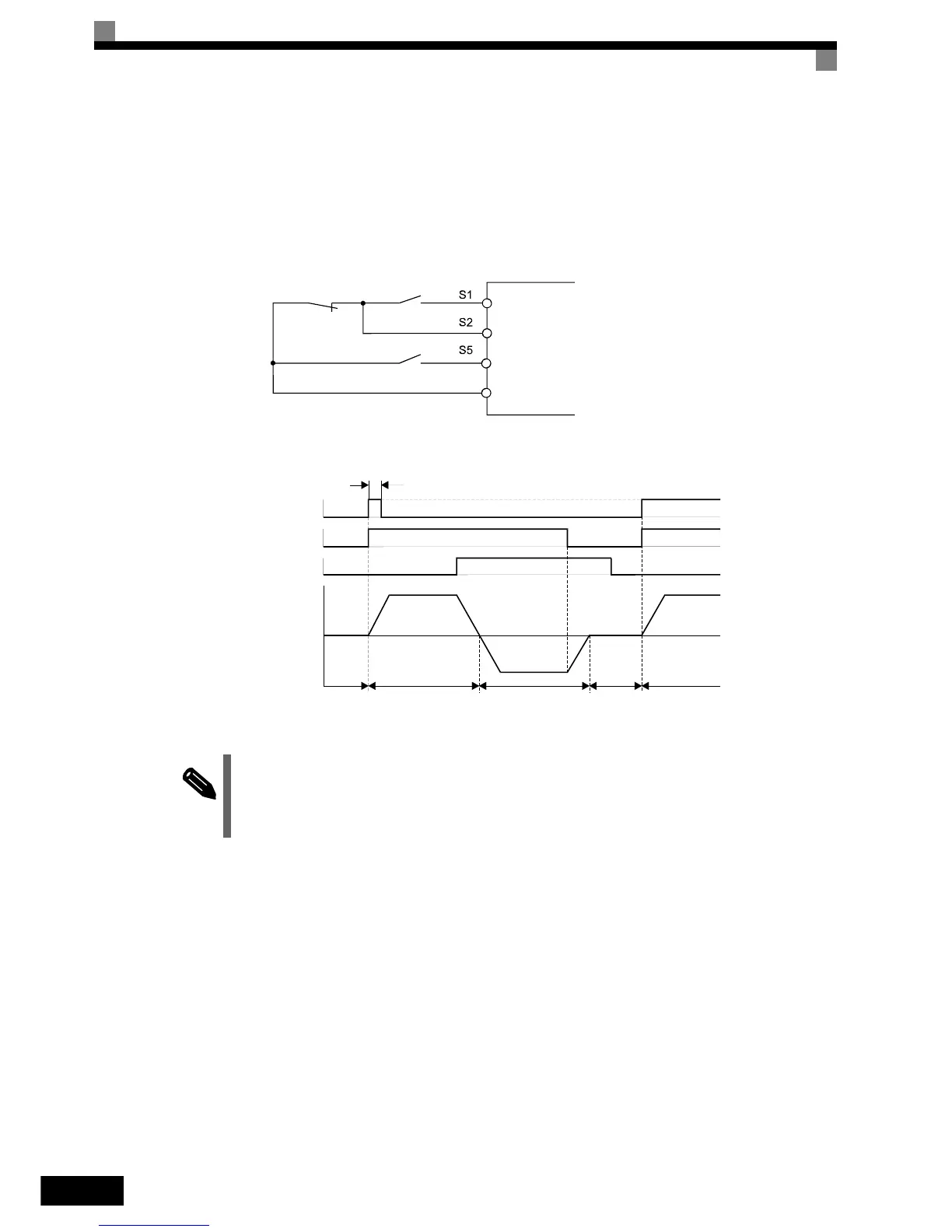
Fig 6.12 3-Wire Control Wiring Example
Fig 6.13 Three-wire Control Time Chart
NOTE
Use a control circuit that turns ON terminal S1 for 50 ms or longer for the run command. This will make
the run command self-holding in the Inverter.
Stop switch
(NC contact)
Operation switch
(NO contact)
Run command (operates when ON)
Stop command (stopped when ON)
Forward/reverse command (multi-function input)
Digital input neutral
SN
50 ms min.
Run command
Forward/reverse command
Motor speed
Can be either ON or OFF
OFF
(stopped)
OFF (forward)
ON (reverse)
Stop Forward Reverse Stop Forward
Stop command