6-18
Time Chart
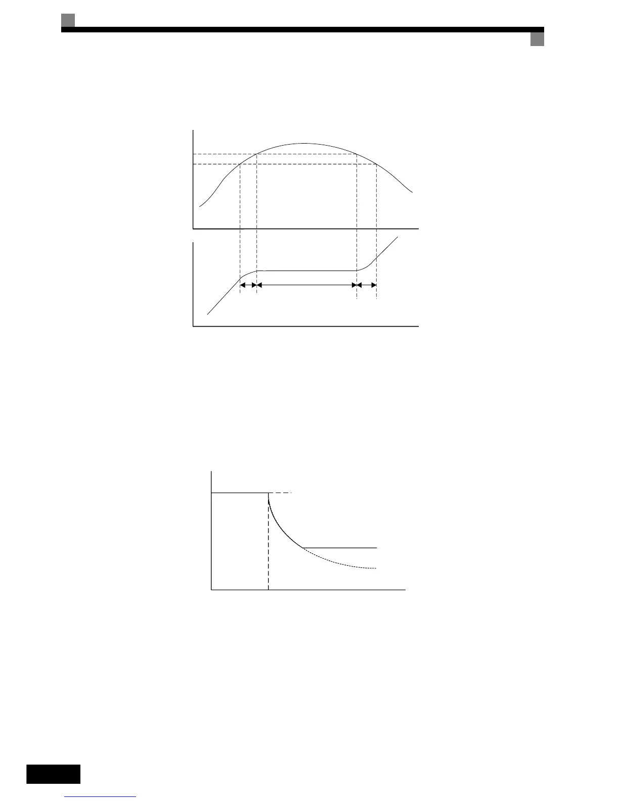
The following figure shows the frequency characteristics when L3-01 is set to 1.
Fig 6.20 Time Chart for Stall Prevention During Acceleration
Setting Precautions
• If the motor capacity is small compared to the Inverter capacity or if the inverter is operated using the fac-
tory settings and the motor stalls, lower the set value of L3-02.
• If using the motor in the field weakening range, L3-02 will be automatically lowered to prevent stalling. It
will be reduced to a fixed value of 50 % of the inverter rated current.
• Set the parameters as a percentage taking the inverter rated current to be 100%.
Fig 6.21 Stall Prevention Level and Limit During Acceleration
Output current
L3-02
85% of
L3-02
Stall level during
acceleration
*1 *2 *3
*1 The acceleration rate is lowered
*2 The acceleration rate is stopped to reduce the output current
*3 The acceleration is restarted
Output frequency
Time
Time
50% of inverter
rated current
L3-02
Stall Prevention Level
during Acceleration
Output frequency
E1-06
Base Frequency (FA)