Machine Protection
6-31
L6-01 Set Value and Digital Operator Display
The relationship between alarms displayed on the Digital Operator when overload or loss of load is detected
and the setting in L6-01 is shown in the following table.
Setting Example
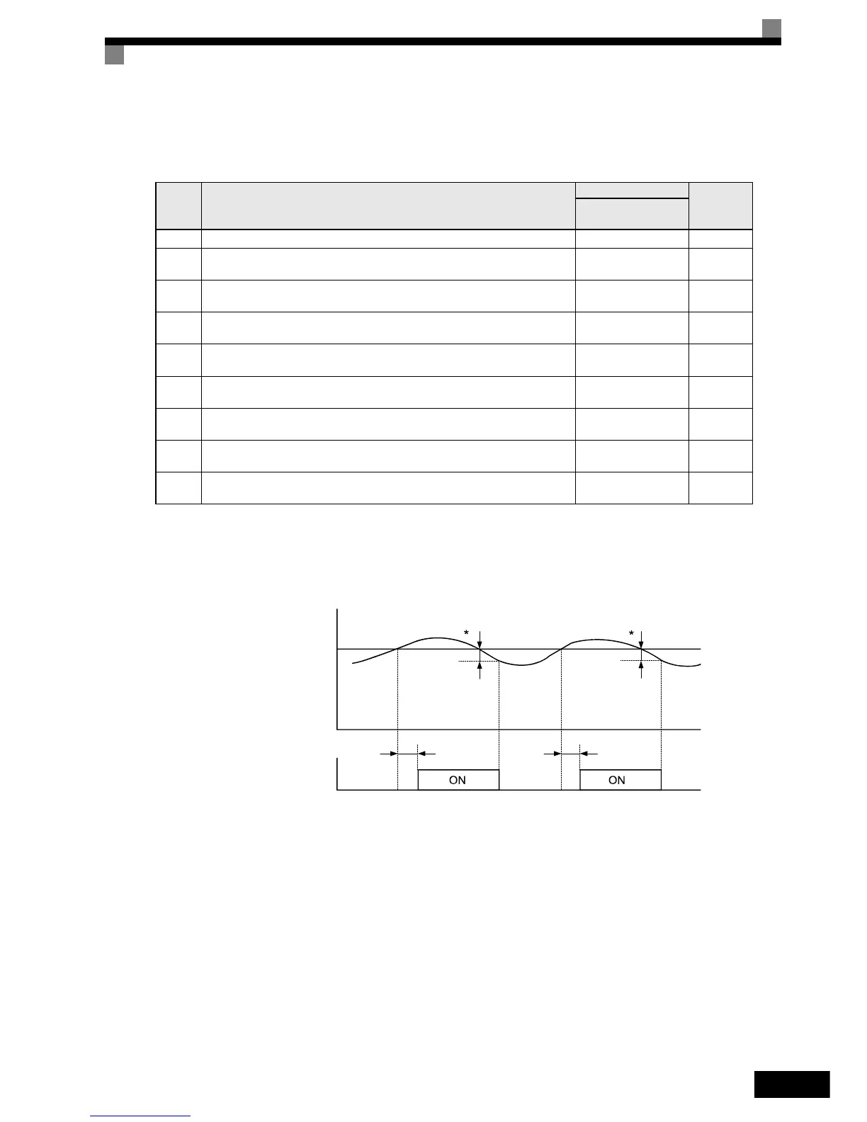
The following diagram shows the time chart for overload and loss of load detection.
• Overload Detection
Fig 6.27 Example Operation for Overload Detection
Set
Value
Function
Operator
Inverter
condition
Overload/Under-
torque Detection 1
0 Load detection disabled – –
1
Overload detection only at speed agree, the operation is continued, a warning is out-
put.
OL3 flashes Alarm
2
Overload detection continuously during operation, operation continues, a warning is
output.
OL3 flashes Alarm
3
Overload detection only at speed agree, motor coasts to stop, Inverter is in fault condi-
tion.
OL3 lights up Fault
4
Overload detection continuously during operation, motor coasts to stop, Inverter is in
fault condition.
OL3 lights up Fault
5
Loss of load detection only at speed agree, the operation is continued, a warning is
output.
LL3 flashes Alarm
6
Loss of load detection continuously during operation, operation continues, a warning
is output.
LL3 flashes Alarm
7
Loss of load detection only at speed agree, motor coasts to stop, Inverter is in fault
condition.
LL3 lights up Fault
8
Loss of load detection continuously during operation, motor coasts to stop, Inverter is
in fault condition.
LL3 lights up Fault
Motor current (output torque)
L6-02
L6-03
L6-03
Load detection 1 NO
* Overload detection switch off bandwidth is approxi-
mately 10% of the Inverter rated output current.