6-36
Operation during Motor Overheating
The operation when the motor overheats can be selected using the parameters L1-03 and L1-04. Set the motor
temperature input filter time parameter in L1-05. If the motor overheats, the OH3 and OH4 error codes will be
displayed on the Digital Operator.
Fault Codes If the Motor Overheats
By setting H3-09 (Multi-function Analog Input Terminal A2 Function Selection) to E (Motor temperature
input) the motor temperature can be detected and OH3 respectively OH4 can be output if the motor overheats.
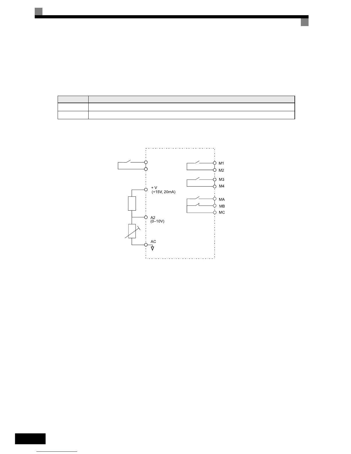
The terminal connections that are to be used are shown in Fig 6.31.
Fig 6.31 Terminal Connections for Motor Overheating Protection
Setting Precautions
Because this function uses a voltage signal to terminal A2, pin 2 of the DIP-switch S1 on the control terminal
board has to be turned to OFF for A2 voltage input. The factory setting is ON (A2 current input). Refer to
Chapter 2, Switch S1 - Standard Terminal Board.
For the same reason the parameter H3-08 (analog input terminal A2 signal level) has to be set to 0 (0-10V
input).
Fault Code Details
OH3 Inverter stops or continues to operate, according to the setting in L1-03.
OH4 Inverter stops according to the setting in L1-04. The fault relay is activated
Inverter
Multi-function
digital input
Branch resistance
18 kΩ
*1
PTC thermistor
Fault relay output
Multi-function
digital output
Multi-function
digital output
* 1. The resistance value of 18 kΩ is only valid when a 3-phase PTC with the characteristic
shown on the previous page is used.