Input Terminal Functions
6-57
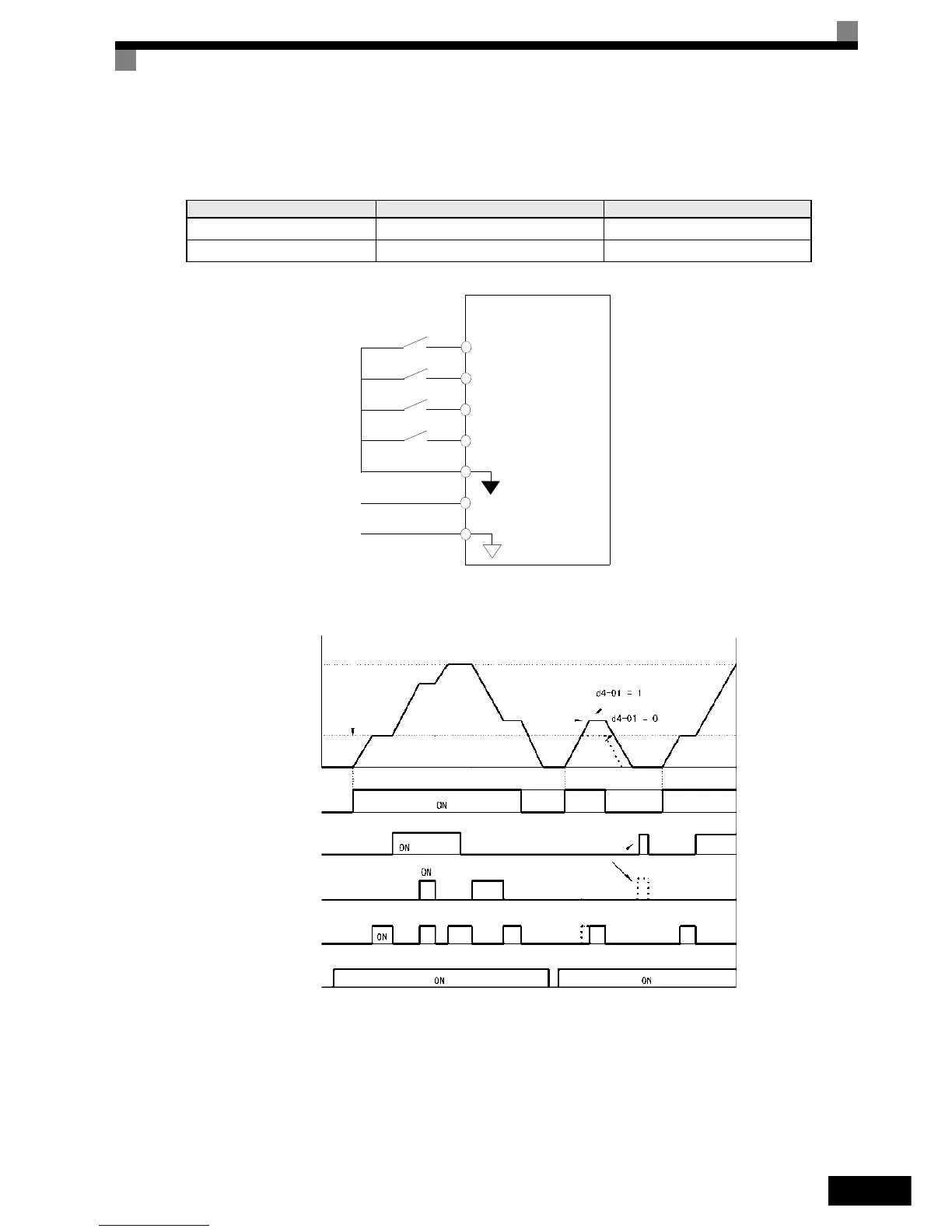
Connection Example and Time Chart
The time chart and settings example when the UP command is allocated to the multi-function Digital Input
terminal S3, and the DOWN command is allocated to terminal S4, are shown below.
Fig 6.44 Connection Example when UP/DOWN Commands Are Allocated
Fig 6.45 UP/DOWN Commands Time Chart
Parameter Name Set Value
H1-01 Multi-function input (terminal S3) 10
H1-02 Multi-function input (terminal S4) 11
Inverter
Forward oper-
ation/Stop
Reverse opera-
tion/Stop
UP command
DOWN command
Digital input
neutral
Frequency refer-
ence lower limit
0 to 10 V analog
signal
S1
S2
S3
S4
SN
A1
AC
Output frequency
Upper limit
Accelerates to
lower limit
Same
frequency
Lower limit
Forward operation/stop
UP command
DOWN command
Speed agree*
Reference
frequency reset
Power supply
* The speed agree signal turns ON when the motor is not accelerating/
decelerating while the RUN command is ON.