Individual Functions
6-75
MEMOBUS Message Example
An example of MEMOBUS command/response messages is given below.
Reading Inverter Memory Register Contents
The content of maximum 16 inverter memory registers can be readout at a time.
Among other things the command message must contain the start address of the first register that is to be read
out and the quantity of registers that should be read out. The response message will contain the content of the
first and the consecutive number of registers that has been set for the quantity.
The contents of the memory register are separated into higher 8 bits and lower 8 bits.
The following tables show message examples when reading status signals, fault details, data link status, and
frequency references from the slave 2 Inverter.
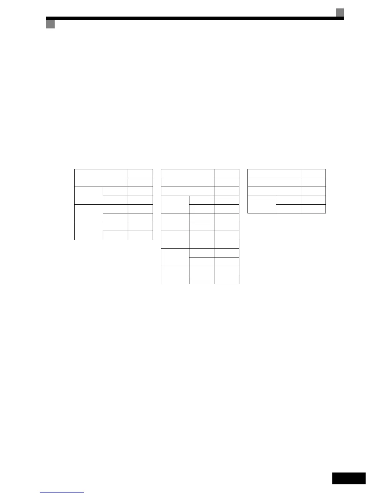
Command Message
Response Message
(During Normal Operation)
Response Message
(During Error)
Slave Address 02H Slave Address 02H Slave Address 02H
Function Code 03H Function Code 03H Function Code 83H
Start
Address
Higher 00H Data quantity 08H Error code 03H
Lower 20H
1st storage
register
Higher 00H
CRC-16
Higher F1H
Quantity
Higher 00H Lower 65H Lower 31H
Lower 04H
Next stor-
age register
Higher 00H
CRC-16
Higher 45H Lower 00H
Lower F0H
Next stor-
age register
Higher 00H
Lower 00H
Next stor-
age register
Higher 01H
Lower F4H
CRC-16
Higher AFH
Lower 82H