8-6
200 V and 400 V Class Inverters of 22 kW or More
A cooling fan is attached to the top panel inside the Inverter.
The cooling fan can be replaced without removing the Inverter from the installation panel.
Removing the Cooling Fan
1. Remove the terminal cover, Inverter cover, Digital Operator, and front cover from the Inverter.
2. Remove the controller bracket to which the cards are mounted. Remove all cables connected to the con-
troler.
3. Remove the cooling fan power cable connector (CN26 and CN27) from the gate driver positioned at the
back of the controller.
4. Remove the fan cover screws and pull out the fan cover from the Inverter.
5. Remove the cooling fan from the fan cover.
Mounting the Cooling Fan
After attaching a new cooling fan, use the above described procedure in reverse order to attach all of the com-
ponents.
When attaching the cooling fan to the mounting bracket, be sure that the air flow direction faces the top of the
Inverter.
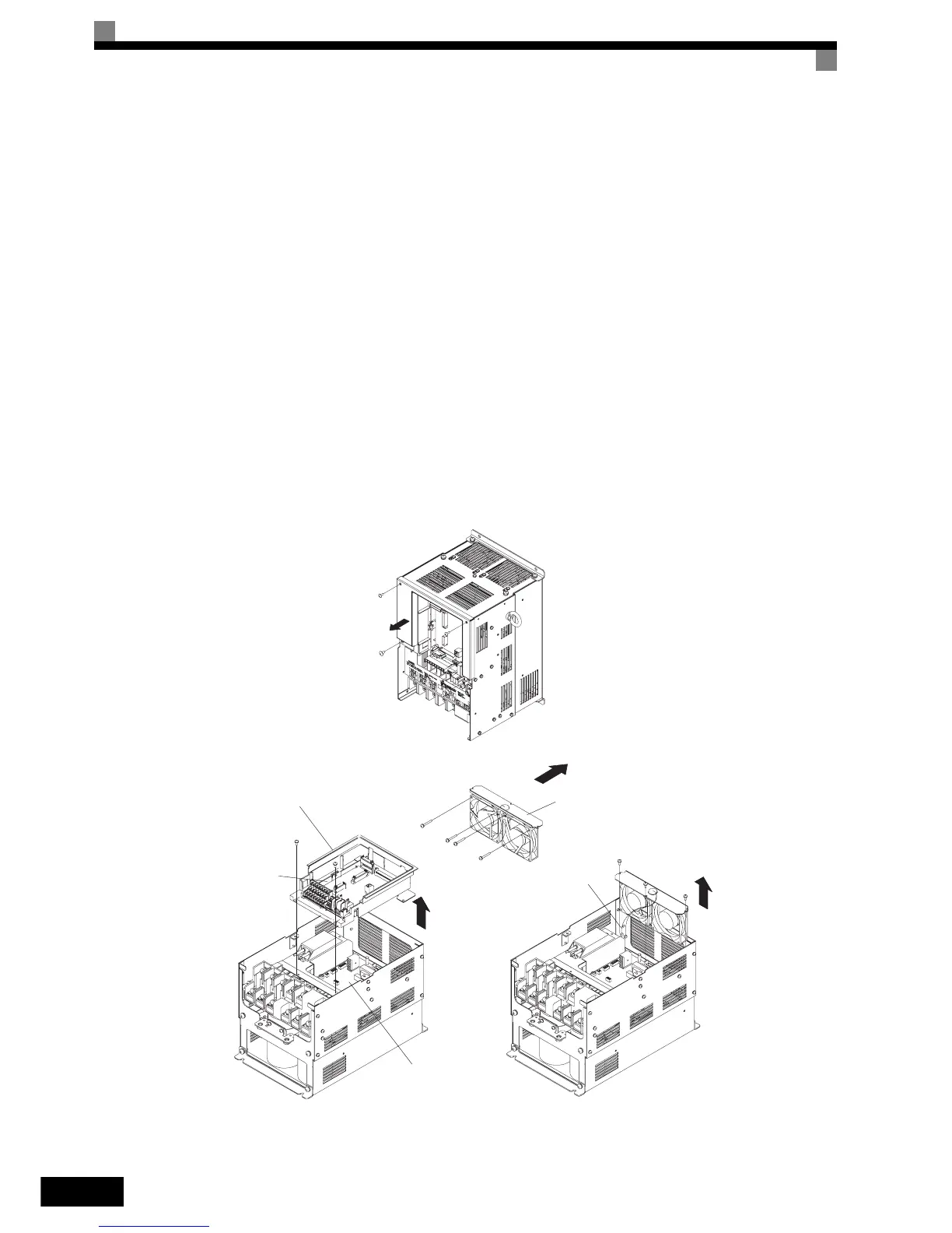
Fig 8.2 Cooling Fan Replacement (Inverters of 22 kW or More)
Controller bracket
Controller
Gate driver
Fan cover
Connector
Air flow direction