3-4
Except in diagrams, Keys are referred to the Key names listed in the above table.
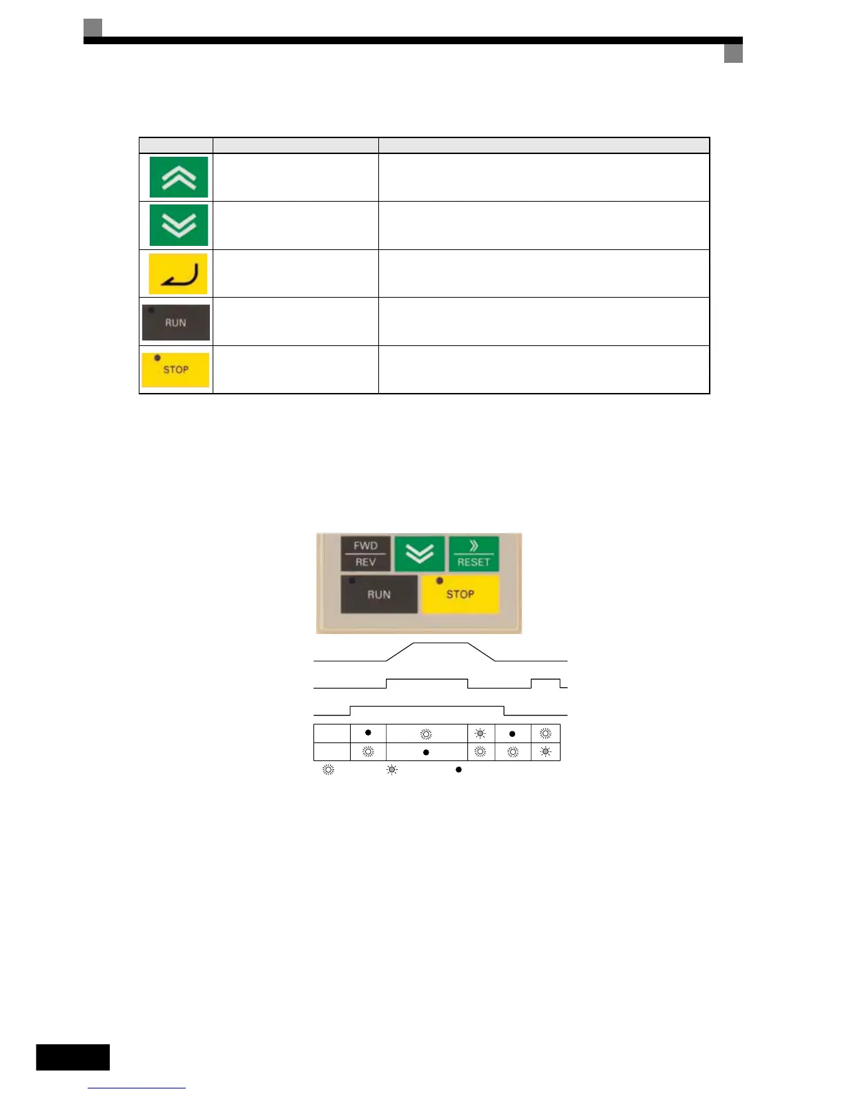
There are indicators on the upper left of the RUN and STOP keys on the Digital Operator. These indicators
will light and flash to indicate the operating status.
The RUN key indicator will flash and the STOP key indicator will light while a DC current is injected in the
motor. The relationship between the indicators on the RUN and STOP keys and the Inverter status is shown in
Fig 3.3.
Fig 3.3 RUN and STOP Indicators
Increment Key
Selects user parameter numbers and increments parameter settings.
Used to move to the next item or data.
Decrement Key
Selects user parameter numbers and decrements parameter settings.
Used to move to the previous item or data.
DATA/ENTER Key Enters menus and parameters and validates parameter settings.
RUN Key
Starts operation when the Inverter is being controlled by the Digital
Operator (LOCAL Mode).
STOP Key
Stops Inverter operation (LOCAL and REMOTE Mode).
This key can be enabled or disabled when operating from a source
different tan the operator by setting parameter o2-02.
Table 3.1 Key Functions
Key Name Function
RUN
STOP
Lit up
Blinking
Not lit up
Output
Frequency
Frequency
Reference
RUN command