ZS4-4 Controller Hardware Overview
Figure Legend Figure Legend
7 Power Supply (PS) Service action required LED
(amber)
15 Solid state drive 4 (optional)
8 Over temperature warning LED (amber) 16 Solid state drive 5 (optional)
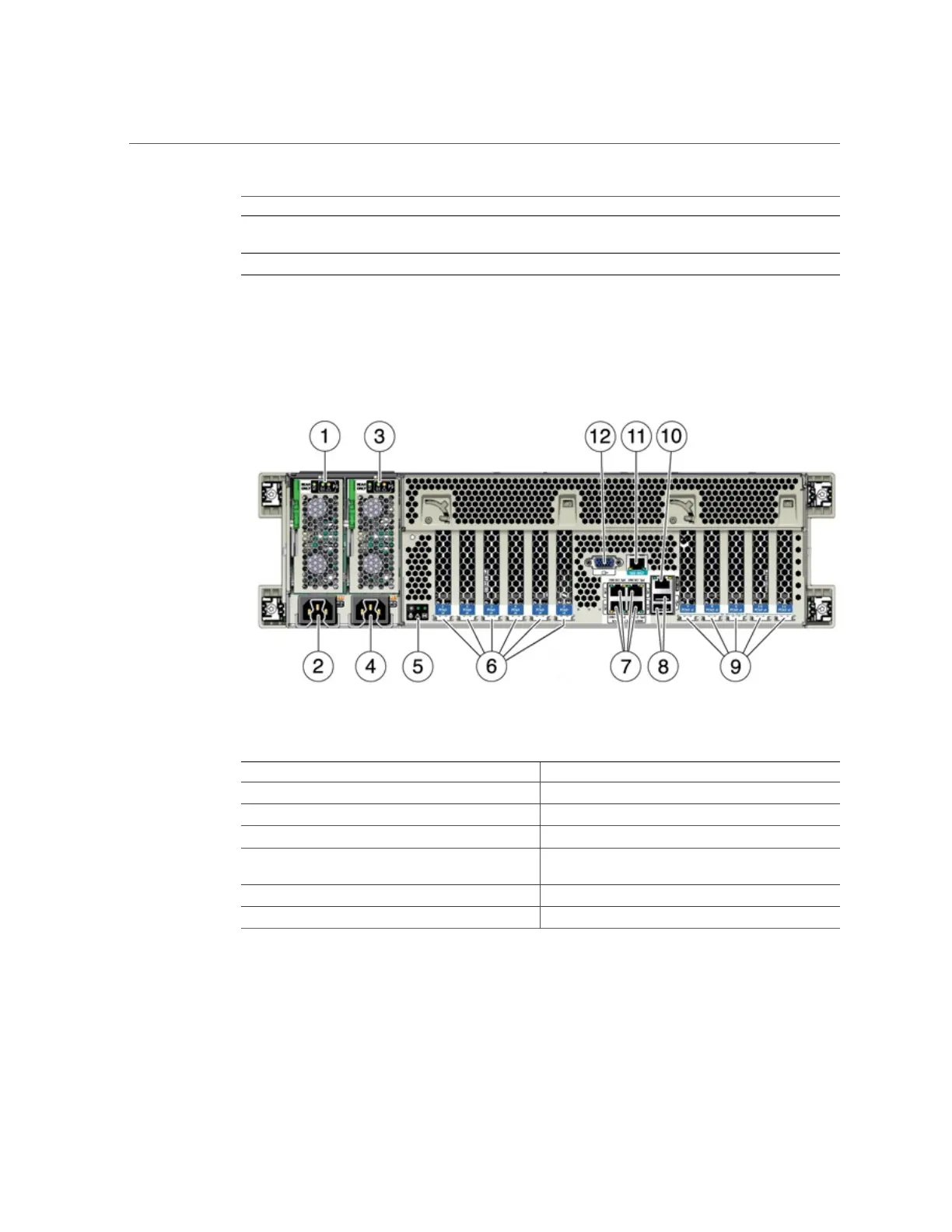
Rear Panel Components - The ZS4-4 rear panel is shown in the following figure. Base
configuration PCIe cards are not depicted in this illustration.
FIGURE 3
ZS4-4 Controller Rear Panel
Figure Legend Figure Legend
1 Power supply unit (PSU) 0 indicator panel 7 Network (NET) 10 GbE ports: NET0NET3
2 PSU 0 AC inlet 8 USB 2.0 connectors (2)
3 PSU 1 indicator panel 9 PCIe card slots 7-11
4 PSU 1 AC inlet 10 Network management (NET MGT) 10/100/1000
BASE-T Ethernet port
5 System status indicator panel 11 Serial management (SER MGT) RJ-45 port
6 PCIe card slots 1-6 12 DB-15 video port
Cluster Interface Card Compatibility - The ZS4-4 controller can contain a Version 2 or
Version 3 cluster interface card. For clustered controllers, ensure you are using the same version
in each controller because these two versions are not compatible.
76 Oracle ZFS Storage Appliance Customer Service Manual • July 2016