OPTIMOD MAINTENANCE
4-9
most frequencies. However, in an emergency it is usually possible to detect many of
the more severe faults that could develop in the 8685 circuitry even in high-RF envi-
ronments.
See the assembly drawings in Section 6 for component locations. Be sure to turn the
power off before removing or installing circuit boards.
Follow these instructions in order without skipping steps.
Note: To unbalance the analog output, connect pin 1 (ground) to pin 3, and meas-
ure between pin 1 (ground) and pin 2 (hot).
Note: All analog output measurements are taken with a 620Ω ±5% resistor tied be-
tween pin 2 and 3 of the XLR connector.
1. Save your existing System Setup.
To facilitate testing the 8685, we supply several Setups to be recalled as you
work through the testing procedure below. Recalling a Setup will cause you to
lose any unsaved adjustments you have made to the 8685’s setup parameters.
Therefore, to allow you to restore your existing settings later, save them as a Sys-
tem Setup before you start testing the 8685. (See step 4 on page 2-21 and step
10 on page 2-30.)
2. Test the power supply
A) If the power supply is entirely dead and the fuse
is not blown, verify that the
primary winding of the power transformer is intact by measuring the resis-
tance of the power supply at the IEC AC line connector.
• For 115-volt operation, the resistance should be approximately 7.6Ω.
• For 230-volt operation, the resistance should be approximately 27Ω.
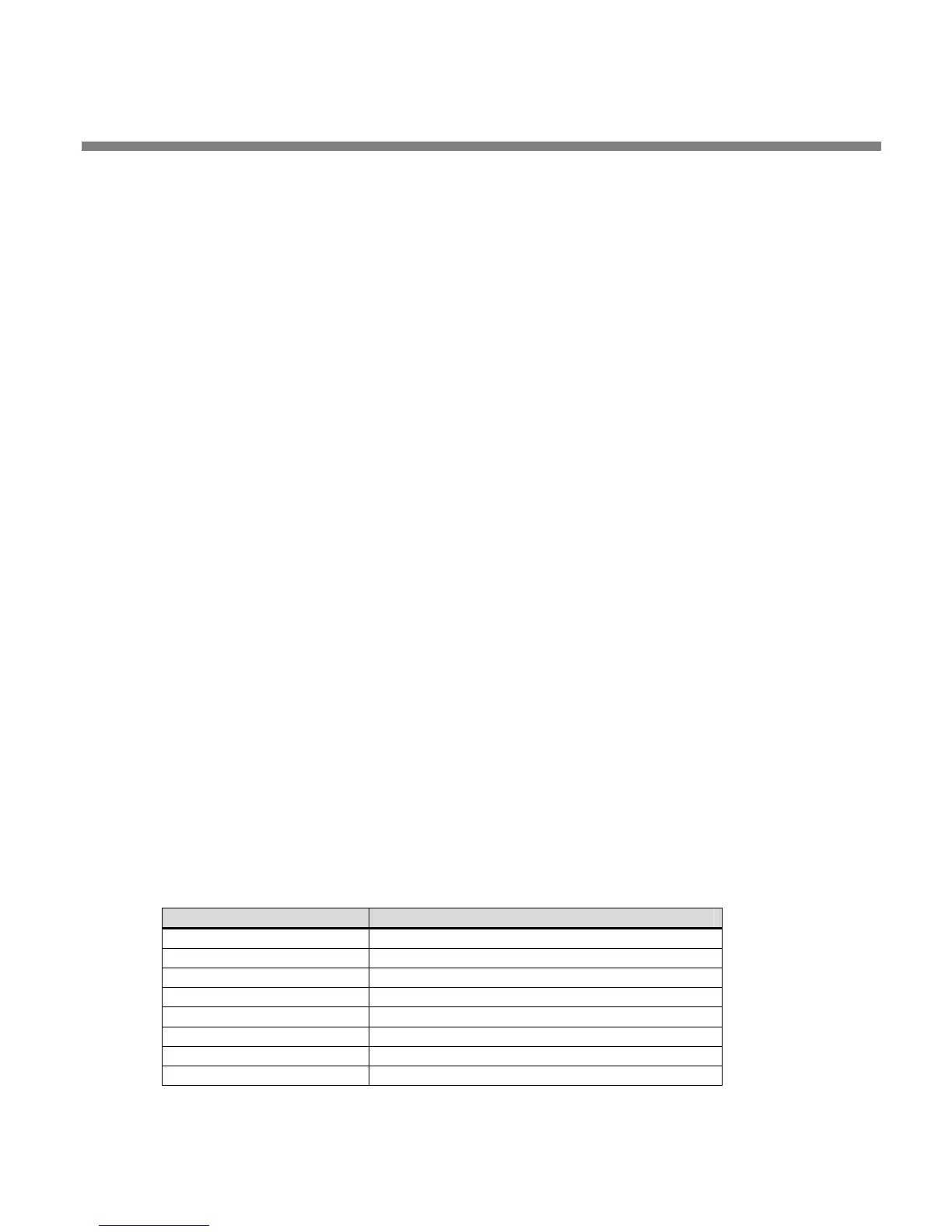
B) The green LED power indicator on the upper right of the front panel display
monitors the DC power supply outputs. If one or more power supply voltages
are out of tolerance, red flashes will report them according to the table be-
low. If there are multiple values out of tolerance, they are reported one after
another in a continuous loop, with one green flash indicating the beginning
of each count.
Number of Red Flashes Problem With
1 + unregulated supply
2 +15V or –15V
3 +5V or –5V
4 +5V Digital
5
Analog
Digital ground connection broken
6 DSP A +3.3V supply
7 DSP B +3.3V supply
8 CPU +3.3V supply