ADF SERIES® OPERATION MANUAL
SECTION 5: UNPACKING AND INSTALLATION
Entire Contents Copyright 2018 by Pacific Power Source, Inc. (PPS) • All Rights Reserved • No reproduction without written authorization from PPS.
ADF Series Power Source Operation Manual Page 44 of 349
Consult the table below for recommended wire size by model number and AC input rating.
INPUT SERVICE
WIRE SIZE, 75°C RATED
480 V ac, 3~
16 A rms, max
20 A rms
4 mm^2 (AWG 12)
480 V ac, 3~
24 A rms, max
30 A rms
6 mm^2 (AWG 10)
480 V ac, 3~
24 A rms, max
30 A rms
6 mm^2 (AWG 10)
Table 5-1: AC Input Wire Size Table
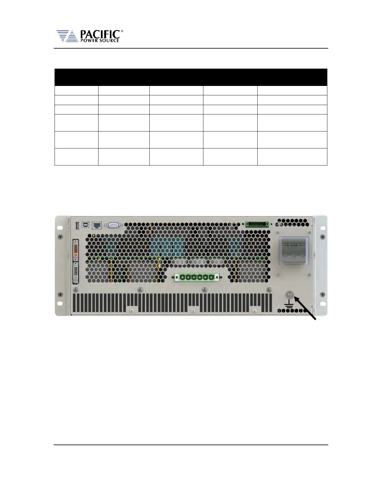
The AC input connections must be made at the rear panel AC terminal block. This input
block has a removable safety cover that must be installed when the instruments is used on a
bench or is otherwise accessible at the rear. If mounted in a cabinet with a locked door or
screen, the AC input safety cover may be omitted if needed.
Figure 5-3: Rear Panel Layout
The AC input terminal phasing is marked on the rear panel and shown in the illustration
below. A four wire mains connection is required. (L1, L2, L3 and Earth Ground). Ground
connection is located directly below the AC Line input terminal block as shown in Figure 5-3
above.
 Loading...