sectton
300~mstatlaf10n
Uapter
4. Trunks and Lines
Installation
1.
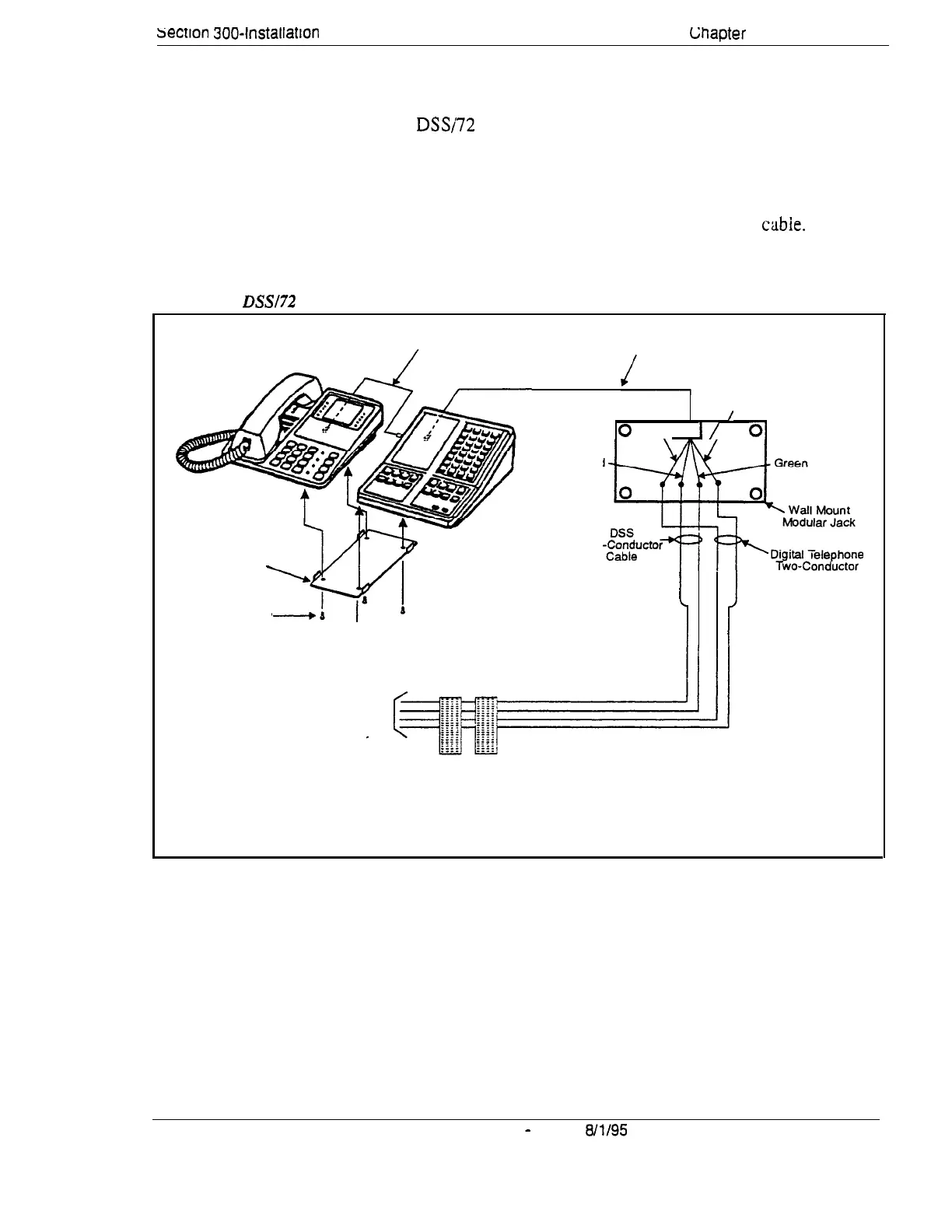
Attach the DSSi72 to the key phone using the mounting plate and the four
screws.
2.
Connect the DSS to the key phone using the two-conductor cable.
3.
Connect the DSS to the wall jack using a four-conductor
cabie.
4.
Connect the four wires from the key phone and DSS to the MDF.
Figure 4-16. DSSl72 connection using one cable with two pairs.
Two-Conductor
Four-Conductor
Cable
Cable
Mounting Plate
_
Flat-Head Screw
Slack Yellow
/
0
\I
I/
01
d
Red
Two
i
i
Cable
To digital extension ports
(Ports 1 and 2 are attendant
phones by default).
Se careful not to reverse
DSS and key phone wiring.
DBS-70-300
DBS Manual
-
Issued
8/l/95
4-41
Technical Manuals Online! - http://www.tech-man.com