FP3 MEWNET-TR
Chapter3-2. Page.45
41
J
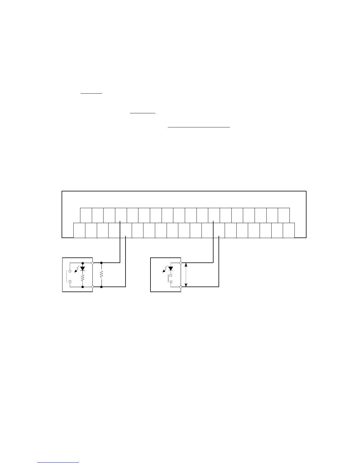
Notes on limit switch and reed switch wiring
<LED-equipped limit switches>
x The use of a bleeder resistor is recommended if the input is not turned OFF or if the LED of the limit switch is kept
ON due to leakage current from the limit switch.
x The OFF voltage of the input is 2.4 V. Therefore, when the power supply voltage is 24 V, select an R value so that the
current will be greater than 2.4 V. The limit switch’s leakage current I is:
I
=
24–2.4
r
r: internal resistor of the limit switch (k:)
The impedance of the input terminal is 4.4 k:.
x The bleeder resistor R is:
R
≦
10.56
4.4
I
–2.4
(k
Ω
)
x The wattage W of the bleeder resistor is:
W
=
(Power supply voltage)
2
R
Actually, use a value that is 3 to 5 times the value of W.
<LED-equipped reed switch>
x When an LED, such as an LED-equipped reed switch, is connected in series with an input point, make the voltage that
is applied to the FP I/O transmitter unit’s input circuit greater than 20.4 V. Take particular care when connecting a
number of switches in series.
r
20.4 V DC
or more
LED
+
24V
-
24V
0123
+
RS
485
+
-
+
-
F.G.
-
RS
485
4567
+
-
+
-
16-input type FP I/O transmitter unit
89AB
+
-
+
-
CDEF
+
-
+
-
Bleeder
resistor
R
LED-equipped
limit switch
LED-equipped
reed switch
3-2. Wiring