21.1.2. Troubleshooting Guide
Symptom Checking Items Repair Items Remarks
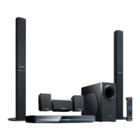
FL display blinking with
abnormal segment when
power ON the set or "F61"
Check the soldering of the SMPS
P. C .B .
·
Is there any solder crack at area
(Q5860,Q5861, Q5862,TH5860,
QR5801)
·
Check all the supply line
30V
·
Is there any solderability at area
of feedback circuit
·
Check feedback circuit (IC5801,
Q5802, D5806, PC5720, D5725)
Tou ch-up the solder crack area/
Change the defective parts.
·
Q5860,Q5861,Q5862,TH5860
(Tem perature Detect)
·
QR5801 & QR5802 ( 30V
Detect)
·
Tou ch-up the necessary areas
·
IC5801, D5806, PC5720,
D5725
SMPS
P. C .B .
Refer to
Fig. 1
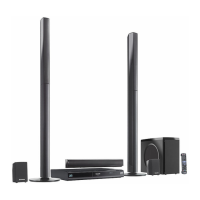
First Power ON Display
immediate show "F61".
Check Speaker output by using
multi-meter,
·
If there is a DC Voltage around
30V
·
Check Output IC (Pin 10 &
14) which have DC Voltage at
Speaker output short to
Vdd/Vss
·
If shorted that means D-Amp
damage already.
Change the defective parts.
D-AMP IC:
IC5000/IC5200/IC5300/IC5400
P/N = C1BA00000487
For Configuration
Refer to Table 1
D-AMP
P. C .B .
Refer to
Fig. 2
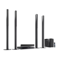
Power ON for a while then
only trigger "F61".
(Symptom always happen)
Check the fan connection &
feedback loop:
·
If the fan not proper connected,
"F61" will trigger when the
volume increase.
·
If the fan is not working, check
for fan circuit.
Check the soldering of the SMPS
P. C .B .
·
Is there any solder crack at area
(Q5860,Q5861, Q5862,TH5860,
QR5801)
·
Check all the supply line
30V
Re-connect the Fan to CN5501
Fan circuit: Q5640, Q5641,
Q5642, Q5644
Tou ch-up the solder crack area/
Change the defective parts.
·
Q5860,Q5861,Q5862,TH5860
(Tem perature Detect)
·
QR5801 & QR5802 (
30V
Detect)
Feedback Circuit: IC5801,
PC5720, D5725
D-AMP
P. C .B .
Refer to
Fig. 3
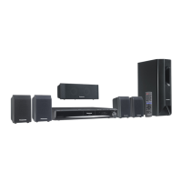
Power ON for a while and
then trigger "F76"
Check all supply voltages as
follows:
Step 1: Check for supply voltages
from SMPS P. C.B to Power Supply
P. C.B at pin 8 & 9 of CN2004. If
there are supply voltages, proceed
to Step 2.
If no voltages detected, check wire
connection and circuitry connection
from SMPS P. C.B.
Step 2: Check if there is supply
voltages for
Vp, F+ & F- at
CN2016
·
If there is supply voltages of
+5.3V, +2.5V (For DVD), +6V
(SYS6V), +9V & +18V at
CN2016
·
If there is supply voltages of
7V at CN6001
Check and change the possible
defective parts.
·
FP2901 (Fuse Protector),
T2900, D2901, D2906, D2908,
D2909
·
IC2903 (DC-DC Converter IC)
& related regulator circuit
components
·
IC2900 (DC-DC Converter IC)
& related regulator circuit
components
Power
Supply
P. C .B
Refer to
Fig. 4
142
SA-BT100P / SA-BT100PC