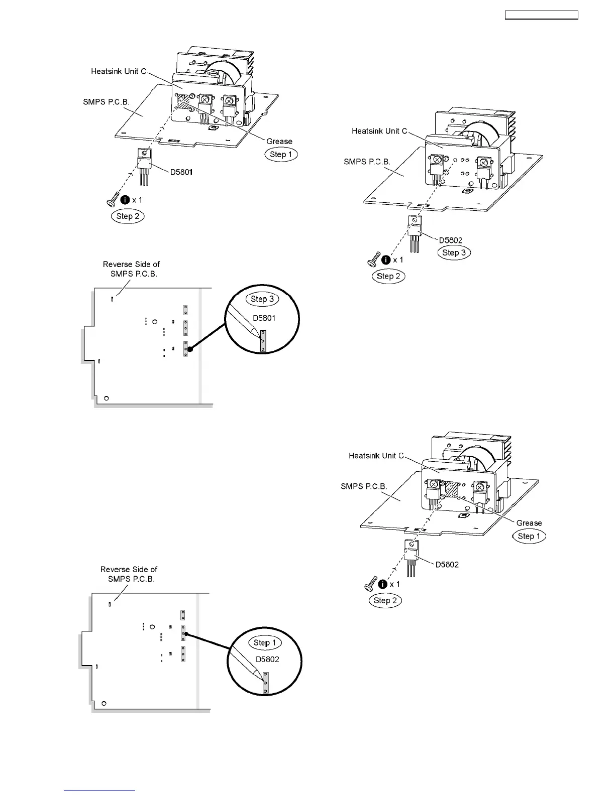
Step 3 Solder pins of the regulator diode (D5801) on the
reverse side of SMPS P.C.B.
Special Note: Ensure pins of the regulator diode (D5801) are
properly seated and soldered on SMPS P.C.B.
10.19. Replacement of Regulator
Diode (D5802)
•
• •
• Follow (Step 1) to (Step 3) of Item 10.3.
•
• •
• Follow (Step 1) to (Step 7) of Item 10.12.
•
• •
• Follow (Step 1) to (Step 6) of Item 10.17.
Step 1 Desolder pins of the regulator diode (D5802) on the
reverse side of SMPS P.C.B.
Step 2 Remove 1 screw from the regulator diode (D5802).
Step 3 Remove the regulator diode (D5802) from the heatsink
unit C.
Caution: Handle the heatsink unit C with caution due to its
high temperature after prolonged use. Touching it may
lead to injuries.
Note: Refer to the diagrams of SMPS P.C.B. (Item 20.7) for
location of the part.
10.19.1. Assembly of Regulator Diode
(D5802)
Step 1 Apply grease to the heatsink unit C.
Step 2 Fix and screw the regulator diode (D5802) to the
heatsink unit C.
Special Note: Ensure the regulator diode (D5802) is tightly
screwed to the heatsink unit C.
Step 3 Solder pins of the regulator diode (D5802) on the
reverse side of SMPS P.C.B.
55
SA-BT100P / SA-BT100PC