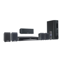
10.3. Disassembly of Top Cabinet
Step 1 Remove 4 screws at the side of the top cabinet.
Step 2 Remove 3 screws at the rear of the top cabinet.
Step 3 Lift up the back part of the top cabinet and remove it in
the direction of arrows.
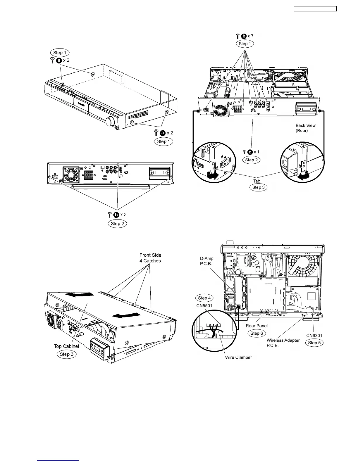
10.4. Disassembly of Rear Panel
•
• •
• Follow (Step 1) to (Step 3) of Item 10.3.
Step 1 Remove 7 screws at the rear panel.
Step 2 Remove 1 screws at the rear panel.
Step 3 Release the tab of each side of the rear panel in the
direction of arrow.
Step 4 Remove the wire clamper to detach the fan unit
connector (CN5501) on D-Amp P.C.B.
Step 5 Detach 19P FFC cable at the connector (CN6301) on
Wireless Adapter P.C.B.
Step 6 Remove the rear panel.
10.5. Disassembly of Front Panel
•
• •
• Follow (Step 1) to (Step 3) of Item 10.3.
Step 1 Detach 14P FFC cable at the connector (CN1101) on
Main P.C.B.
Step 2 Detach 24P FFC cable at the connector (CN806) on
Main P.C.B.
Step 3 Detach 13P FFC cable at the connector (P58005) on
43
SA-BT100P / SA-BT100PC