•
• •
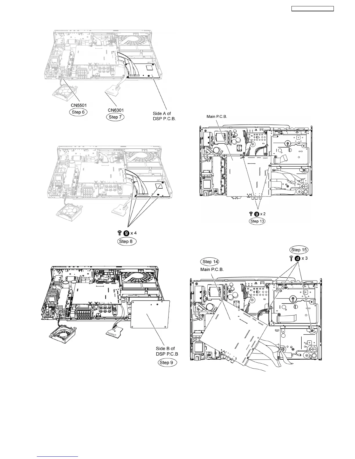
• Servicing side B of DVD Module P.C.B.
Step 8 Remove 4 screws on DSP P.C.B.
Step 9 Flip DSP P.C.B to its side B and position it to the
diagram show.
12.5. Checking & Repairing Digital
P.C.B.
•
• •
• Servicing Side A of Digital P.C.B.
Step 1 Remove the top cabinet.
Step 2 Remove the front panel.
Step 3 Remove the panel P.C.B.
Step 4 Remove the headphone P.C.B.
Step 5 Remove open/close P.C.B.
Step 6 Remove Power Button P.C.B.
Step 7 Remove SD P.C.B.
Step 8 Remove i-Pod P.C.B.
Step 9 Remove Wireless Adapter P.C.B.
Step 10 Remove Rear Panel (Remove all screws).
Step 11 Remove the Fan Unit.
Step 12 Remove the DSP P.C.B.
Step 13 Remove the BD Drive.
Step 14 Remove 2 screws on Main P.C.B.
Step 15 Move aside main P.C.B as the diagram show.
Step 16 Remove 3 screws at the mechanism angle.
Step 17 Position mechanism angle according to the diagram
show.
Step 18 Position Main P.C.B according to diagram show.
Step 19 Attach original cable with extension cable RFKZ0491
(17P cable from CN5050 to CN503).
Step 20 Attach original cable with extension cable RFKZ0490
(22P cable from CN804 to CN58002).
65
SA-BT100P / SA-BT100PC